EasyManua.ls Logo

Sharp CD-C7000W

Sharp CD-C7000W
68 pages
To Next Page IconTo Next Page
Loading...
– 1 –
CD-K7000W/C7000W,CP-C7000
No. S3022CDK7000W
CONTENTS
Page
SAFETY PRECAUTION FOR SERVICE MANUAL ........................................................................................................... 2
VOLTAGE SELECTION ..................................................................................................................................................... 2
SPECIFICATIONS ............................................................................................................................................................. 3
NAMES OF PARTS ........................................................................................................................................................... 4
OPERATION MANUAL ...................................................................................................................................................... 8
DISASSEMBLY.................................................................................................................................................................. 9
REMOVING AND REINSTALLING THE MAIN PARTS ................................................................................................... 12
ADJUSTMENT ................................................................................................................................................................. 14
NOTES ON SCHEMATIC DIAGRAM .............................................................................................................................. 16
BLOCK DIAGRAM ........................................................................................................................................................... 17
SCHEMATIC DIAGRAM / WIRING SIDE OF P.W.BOARD ............................................................................................. 21
VOLTAGE ........................................................................................................................................................................ 40
WAVEFORMS OF CD CIRCUIT ...................................................................................................................................... 41
TROUBLESHOOTING (CD SECTION) ........................................................................................................................... 42
FUNCTION TABLE OF IC................................................................................................................................................ 46
FL DISPLAY ..................................................................................................................................................................... 54
REPLACEMENT PARTS LIST/EXPLODED VIEW
CD-K7000W
CD-C7000W
CP-C7000
In the interests of user-safety the set should be restored to its
original condition and only parts identical to those specified be
used.
SERVICE MANUAL
This document has been published to be used
for after sales service only.
The contents are subject to change without notice.
SHARP CORPORATION
Illustration: CD-K7000W/CP-C7000
Illustration: CD-C7000W/CP-C7000
DIFFERENCE BETWEEN CD-K7000W AND CD-C7000W
CD-K7000W
CD-C7000W
Karaoke
Question and Answer IconNeed help?

Do you have a question about the Sharp CD-C7000W and is the answer not in the manual?

Sharp CD-C7000W Specifications

General IconGeneral
BrandSharp
ModelCD-C7000W
CategoryStereo System
LanguageEnglish

Summary

Safety Precautions for Service Manual

Warnings

Crucial safety warnings for handling the laser component during servicing.

Caution Notes

Important notes and warnings regarding laser exposure and cabinet disassembly.

Voltage Selection

Instructions for selecting the correct AC voltage for the unit.

Specifications

CD-K7000 WC7000 W Specifications

Detailed technical specifications for the CD-K7000W/C7000W models.

CP-C7000 Speaker Specifications

Technical specifications for the CP-C7000 speaker system.

Names of Parts

CD-K7000 W Front Panel Parts

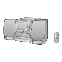
Identification of front panel components for the CD-K7000W model.

CD-C7000 W Front Panel Parts

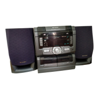
Identification of front panel components for the CD-C7000W model.

Rear Panel and Speaker Components

Identification of rear panel and CP-C7000 speaker components.

Remote Control Buttons

Identification of remote control buttons for CD-K7000W and CD-C7000W models.

Operation Manual

Preparation for Use

Initial setup steps, including AM/FM interval setting and remote control usage.

Setting the Clock

Step-by-step instructions for setting the unit's clock time and display modes.

Resetting the Microcomputer

Procedure for resetting the microcomputer and clearing stored data.

Disassembly

Disassembly Precautions

Important safety and handling notes before disassembling the unit.

CD-K7000 WC7000 W Disassembly Steps

Detailed steps for disassembling the CD-K7000W/C7000W unit.

Removing and Reinstalling Main Parts

Tape Mechanism Section

Procedures for removing and reinstalling tape mechanism components.

CD Mechanism Section

Procedures for removing and reinstalling CD mechanism components.

Adjustment

Mechanism Section Adjustments

Procedures for checking and adjusting mechanism section parameters.

Tuner Section Adjustments

Procedures for adjusting tuner section signal generators and frequencies.

CD Section

CD Adjustment Functions

Overview of automatic adjustment functions for the CD player section.

Notes on Schematic Diagram

Resistor and Capacitor Code Explanations

Explanations of symbols and codes used for resistors and capacitors.

Voltage

IC Voltage Tables

Tables listing voltage readings for various ICs in the system.

Waveforms of CD Circuit

CD Circuit Waveform Analysis

Visual representations and analysis of CD circuit waveforms for troubleshooting.

Trouble Shooting

CD Section Issues

Steps for diagnosing and resolving issues when the CD section does not function.

Focus-HF System Check

Steps for checking the focus-HF system when "NO DISC" is displayed.

Tracking System Check

Steps for checking the tracking servo activation and TE waveform.

Spin System Check

Procedures for verifying the turntable rotation and spin driver circuit.

PLL System Check

Steps for checking the PLL system when TOC data cannot be read.

Sound Output Issues

Steps for diagnosing issues with sound output or dropouts.

Function Table of IC

IC1 Servo Amp. (LA9235 M) Function Table

Detailed pin functions and descriptions for IC1 Servo Amp.

IC2 ServoSignal Control (LC78641 E) Function Table

Detailed pin functions and descriptions for IC2 Servo/Signal Control.

IC701 System Microcomputer (IX0334 AW) Function Table

Detailed pin functions and descriptions for IC701 System Microcomputer.

IC3 FocusTrackingSpinSlide Driver (M63001 FP) Function Table

Detailed pin functions and descriptions for IC3 Driver.

IC601 Audio Processor (LC75341) Function Table

Detailed pin functions and descriptions for IC601 Audio Processor.

ICK1 Mic Amp. (M65856 SP) Function Table

Detailed pin functions and descriptions for ICK1 Mic Amp.

Sharp Parts Guide

How to Order Replacement Parts

Instructions and contact information for ordering replacement parts.

Component Code Explanations

Codes and meanings for capacitor, resistor, and other component part identification.

Part Lists

Lists of integrated circuits, transistors, diodes, filters, transformers, coils, and variables with part codes.

Cabinet, Mechanism, and Accessory Parts

Lists of replacement cabinet, CD mechanism, and accessory parts with codes.

PWB Assemblies and Speaker Parts

Lists of replacement PWB assemblies and speaker box parts with codes.

Other Service Parts

List of other service parts, including labels and manuals.

Related product manuals