EasyManua.ls Logo

Sharp CD-C612 User Manual

Sharp CD-C612
60 pages
To Next Page IconTo Next Page
Page #1 background imageLoading...
Page #1 background image
– 1 –
CD-C612
No. S3910CDC612//
CONTENTS
Page
IMPORTANT SERVICE NOTES (For U.S.A. Only) ........................................................................................................... 2
SPECIFICATIONS ..............................................................................................................................................................2
NAMES OF PARTS ........................................................................................................................................................... 3
OPERATION MANUAL ...................................................................................................................................................... 5
QUICK GUIDE ................................................................................................................................................................... 6
DISASSEMBLY.................................................................................................................................................................. 7
REMOVING AND REINSTALLING THE MAIN PARTS ................................................................................................... 10
ADJUSTMENT ................................................................................................................................................................. 10
NOTES ON SCHEMATIC DIAGRAM .............................................................................................................................. 13
WAVEFORMS OF CD CIRCUIT ...................................................................................................................................... 14
BLOCK DIAGRAM ........................................................................................................................................................... 15
SCHEMATIC DIAGRAM / WIRING SIDE OF P.W.BOARD..............................................................................................18
VOLTAGE .........................................................................................................................................................................32
TROUBLESHOOTING (CD SECTION) ........................................................................................................................... 33
FUNCTION TABLE OF IC................................................................................................................................................ 38
FL DISPLAY ......................................................................................................................................................................45
REPLACEMENT PARTS LIST/EXPLODED VIEW
PACKING OF THE SET (For U.S.A. Only)
CD-C612
In the interests of user-safety the set should be restored to its
original condition and only parts identical to those specified be
used.
SERVICE MANUAL
This document has been published to be used
for after sales service only.
The contents are subject to change without notice.
SHARP CORPORATION
CD-C612 mini component system consisting of CD-C612 (Main unit),
CP-C612 (Front speaker) and GBOXS0024AWM1 (rear speaker ).
Question and Answer IconNeed help?

Do you have a question about the Sharp CD-C612 and is the answer not in the manual?

Sharp CD-C612 Specifications

General IconGeneral
BrandSharp
ModelCD-C612
CategoryStereo System
LanguageEnglish

Summary

Service Notes and Specifications

Important Service Notes

Crucial safety instructions and checks for servicing the audio product.

Technical Specifications

Detailed technical data and performance characteristics of the CD-C612 system.

Front Panel Parts Identification

Front Panel Controls and Indicators

Identifies buttons, lights, and displays on the front panel for user interaction.

Rear, Speaker, and Remote Parts

Rear Panel Connections

Details the ports and connectors on the rear of the main unit.

Speaker Component Identification

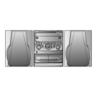
Identifies the parts of the front and rear speaker units.

Remote Control Layout

Lists and labels the buttons and indicators on the remote control unit.

Operation and Setup Procedures

Setting the Clock and System Reset

Guides for setting the clock time and performing a microcomputer reset.

Quick Guide for Basic Operation

Initial Setup and Operation

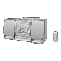
A concise guide for basic setup and initial operation of the system.

Disassembly and Maintenance

Unit Disassembly Steps

Step-by-step instructions for safely taking the unit apart for servicing.

Main Part Removal and Reinstallation

Procedures for detaching and reattaching major components like the CD mechanism.

Adjustment Procedures

Guides for calibrating and tuning the unit's functions, e.g., tape speed.

Circuitry and Diagnostic Information

Tuner Section and Error Codes

Details tuner adjustments and describes common CD error codes for diagnostics.

Test Modes and Signal Waveforms

Instructions for entering test modes and analyzing critical signal waveforms for troubleshooting.

Block Diagrams and Voltage Charts

High-level system overview diagrams and a table of voltage measurements for testing.

Schematic Diagrams

Detailed electrical circuit diagrams essential for repair and analysis.

Troubleshooting and Problem Diagnosis

CD Section Fault Diagnosis

Systematic steps to identify and resolve issues related to the CD player functionality.

Integrated Circuit (IC) Functionality

IC Function Tables and Block Diagrams

Explains the pin functions, purposes, and internal block diagrams of key integrated circuits.

FL Display Information

FL Display Pinout and Segments

Details the pin connections and segment assignments for the front panel FL display.

Parts Identification Guide

Explanation of Capacitor and Resistor Codes

Explains the coding system used for identifying capacitors and resistors.

Replacement Parts List

Comprehensive Parts Listing

A detailed list of all replaceable parts with codes, descriptions, and pricing ranks.

Exploded Views of Components

CD Mechanism Exploded View

A visual diagram showing the assembly of the CD mechanism parts.

Cabinet Exploded Views

Visual diagrams illustrating the assembly of the unit's cabinet and internal structures.

Speaker Exploded Views

Visual diagrams showing the assembly of the CP-C612 and GBOXS0024AWM1 speaker parts.

Packaging Instructions

Packing the Set for Shipping (U.S.A.)

Instructions for properly packaging the unit for shipping or sale, including accessory placement.

Related product manuals