EasyManua.ls Logo

Sharp CD-C290X User Manual

Sharp CD-C290X
56 pages
To Next Page IconTo Next Page
Page #1 background imageLoading...
Page #1 background image
– 1 –
CD-C290X
SERVICE MANUAL
No. S9910CDC290X
CONTENTS
Page
SAFETY PRECAUTION FOR SEVICE MANUAL............................................................................................................. 2
VOLTAGE SELECTION.................................................................................................................................................... 2
SPECIFICATIONS ............................................................................................................................................................ 3
NAMES OF PARTS .......................................................................................................................................................... 4
OPERATION MANUAL..................................................................................................................................................... 6
DISASSEMBLY..................................................................................................................................................................7
REMOVING AND REINSTALLING THE MAIN PARTS.................................................................................................... 9
ADJUSTMENT................................................................................................................................................................ 10
NOTES ON SCHEMATIC DIAGRAM ............................................................................................................................. 12
BLOCK DIAGRAM .......................................................................................................................................................... 13
WAVEFORMS OF CD CIRCUIT..................................................................................................................................... 16
SCHEMATIC DIAGRAM / WIRING SIDE OF P.W.BOARD.............................................................................................17
TROUBLESHOOTING (CD CHANGER CONTROL / CD SECTION) ............................................................................ 34
FUNCTION TABLE OF IC .............................................................................................................................................. 38
FL DISPLAY.....................................................................................................................................................................45
REPLACEMENT PARTS LIST/EXPLODED VIEW
SHARP CORPORATION
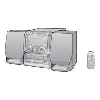
CD-C290X mini component system consisting of
CD-C290X mini component system,CP-C290
speaker system.
In the interests of user-safety the set should be restored to its
original condition and only parts identical to those specified be
used.
CD-C290X
This document has been published to be used
for after sales service only.
The contents are subject to change without notice.
SRS technology Licensed from SRS Labs. SRS technol-
ogy holds the following patents: U.S. Patent No.
4,748,669 and U.S. Patent No. 4,841,572.
SRS, the SRS Logo () and the Sound Retrieval System
are registered trademarks of SRS Labs, Inc. in the United
States.

Questions and Answers:

Sharp CD-C290X Specifications

General IconGeneral
BrandSharp
ModelCD-C290X
CategoryStereo System
LanguageEnglish

Summary

Safety Precautions for Service Manual

Voltage Selection

Describes the function and adjustment of the voltage selector.

Specifications Overview

General Specifications

Details power source, consumption, dimensions, and weight.

Amplifier Section Specifications

Details output power and input/output terminals.

Compact Disc Player Specifications

Details CD player type, signal readout, and D/A converter.

Speaker Section Specifications

Details speaker type, input power, and impedance.

Tuner Section Specifications

Details frequency range for FM and AM.

Cassette Deck Section Specifications

Details frequency response, signal/noise ratio, and wow/flutter.

Names of Parts Identification

Front Panel Parts

Lists and identifies components on the front panel of the main unit.

Rear Panel Parts

Lists and identifies components on the rear panel of the main unit.

Speaker System Parts

Lists and identifies parts of the CP-C290 speaker system.

Remote Control Parts

Lists and identifies buttons and sections of the remote control transmitter.

Operation Manual and System Reset

Setting the Clock

Step-by-step guide to set the unit's clock time.

Resetting the Microcomputer

Procedure to reset the system's memory and settings.

Disassembly Procedures

Caution on Disassembly

Important safety precautions to follow during disassembly and reassembly.

Removing Main Parts

CD Mechanism Removal

Instructions for removing the CD mechanism and its components.

Loading Motor Removal

Steps to remove the loading motor from the CD mechanism.

Pickup Removal

Steps to remove the laser pickup from the CD mechanism.

Adjustment Procedures

Mechanism Section Adjustments

Procedures for checking and adjusting mechanism torque and speed.

Tuner Section Adjustments

Procedures for adjusting tuner IF/RF and FM mute level.

Test Mode Operations

Setting the Test Mode

Method to activate the various test modes available on the unit.

CD Test Mode Function

Details the specific CD operational test mode and pickup movement.

CD Section Automatic Adjustment

Information on automatic adjustment functions within the CD section.

Schematic Diagram Notes

Explanation of Component Codes

Explains the codes used for capacitors and resistors in the parts list.

Schematic Diagram General Notes

Provides general notes and safety information related to schematic diagrams.

Block Diagrams Overview

Pickup Unit Block Diagram

Illustrates the functional blocks within the pickup unit.

CD Motor PWB-F Block Diagram

Shows the connections and functions related to the CD motor PWB.

Block Diagrams Part 2

Tuner and Cassette Block Diagrams

Illustrates the functional blocks for the tuner and cassette deck sections.

Block Diagrams Part 3

System Control and Audio Blocks

Shows functional blocks for system control, audio processing, and power amplification.

CD Circuit Waveform Analysis

CD Circuit Waveform Examples

Displays various waveform examples for CD circuit analysis and troubleshooting.

Printed Wiring Board Wiring Diagrams

Display and Switch PWB Wiring

Shows the wiring layout for the Display PWB (A2) and Switch PWB (A3).

Printed Wiring Board Wiring Diagrams Part 2

Headphone, Power, and Tape Mechanism PWB Wiring

Illustrates wiring for Headphone, Power, and Tape Mechanism PWBs.

Printed Wiring Board Wiring Diagrams Part 3

Main PWB-A1 Wiring Diagram

Detailed wiring layout for the Main PWB (A1).

Printed Wiring Board Wiring Diagrams Part 4

Power PWB and Tape Mechanism Wiring

Shows wiring details for the Power PWB and Tape Mechanism assembly.

Printed Wiring Board Wiring Diagrams Part 5

Pickup, CD Motor, and Sensor PWB Wiring

Illustrates wiring for Pickup Unit, CD Motor PWB, and Sensor PWB.

Printed Wiring Board Wiring Diagrams Part 6

Tuner and SRS PWB Wiring

Shows wiring details for the Tuner PWB and SRS PWB.

Schematic Diagrams Overview

IC Pin Voltage Tables

Lists pin numbers and their corresponding voltage readings for various ICs.

Schematic Diagrams Part 2

Audio Processor and Tape Mechanism Schematics

Detailed schematic diagrams for the audio processor and tape mechanism.

Schematic Diagrams Part 3

Main PWB and Signal Schematics

Schematic diagrams for the Main PWB and various signal paths.

Schematic Diagrams Part 4

Servo Amplifier Schematic Diagram

Detailed schematic diagram for the Servo Amplifier IC.

Schematic Diagrams Part 5

System Microcomputer and Loading Motor Schematics

Schematic diagrams for the system microcomputer and loading motor driver.

Schematic Diagrams Part 6

Power Amplifier and Voltage Regulator Schematics

Schematic diagrams for power amplifier and voltage regulator circuits.

Schematic Diagrams Part 7

Headphone and Power PWB Schematics

Schematic diagrams for the headphone and power supply PWBs.

Schematic Diagrams Part 8

Tape Mechanism and Microcomputer Connections

Schematic diagrams for tape mechanism and system microcomputer connections.

Schematic Diagrams Part 9

Display and Switch PWB Schematics

Schematic diagrams for the display and switch PWBs.

Schematic Diagrams Part 10

Tuner PWB Schematic Diagram

Detailed schematic diagram for the Tuner PWB.

Schematic Diagrams Part 11

SRS PWB Schematic Diagram

Detailed schematic diagram for the SRS PWB.

CD Section Troubleshooting

CD Section Not Functioning

Steps to diagnose and fix when the CD section fails to operate.

Turntable Fails to Stop

Troubleshooting steps when the turntable fails to stop rotating correctly.

Turntable Fails to Move

Troubleshooting steps when the turntable fails to move or rotate.

CD Troubleshooting Continued

CD Tray Fails to Open or Close

Steps to diagnose and fix CD tray opening or closing problems.

CD Function Will Not Work

Steps to diagnose and fix when the entire CD function does not work.

CD Operating Keys Functionality

Checks related to CD operating keys and focus/HF systems.

CD Troubleshooting Further Checks

Playback Requires Disc

Confirms that playback is only possible with a loaded disc.

Tracking System Checks

Procedures to check the tracking system's performance and associated components.

CD Troubleshooting System Checks

Checking the Spin System

Steps to diagnose issues with the disc spin system.

Checking the VCO-PLL System

Procedures to check the VCO-PLL system for TOC data reading issues.

Troubleshooting No Sound Output

Diagnosing no sound issues when HF waveform and time indication are normal.

Integrated Circuit Function Tables

IC2 Servo/Signal Control Function Table

Details the function of each pin for the IC2 Servo/Signal Control IC.

Integrated Circuit Function Tables Continued

IC2 Block Diagram

Illustrates the internal block diagram of the IC2 Servo/Signal Control IC.

Integrated Circuit Function Tables Part 2

IC1 Servo Amplifier Function Table

Details the function of each pin for the IC1 Servo Amplifier IC.

Integrated Circuit Function Tables Part 3

IC1 Block Diagram

Illustrates the internal block diagram of the IC1 Servo Amplifier.

Integrated Circuit Function Tables Part 4

IC701 System Microcomputer Function Table

Details the function of each pin for the IC701 System Microcomputer.

Integrated Circuit Function Tables Part 5

IC701 Block Diagram

Illustrates the internal block diagram of the IC701 System Microcomputer.

Integrated Circuit Function Tables Part 6

IC201 SRS Function Table

Details the function of each pin for the IC201 SRS IC.

Integrated Circuit Function Tables Part 7

IC5 Driver Function Table

Details the function of each pin for the IC5 Driver IC.

Sharp Parts Guide

How to Order Replacement Parts

Instructions on how to order replacement parts by providing necessary information.

Explanation of Component Codes

Explains the codes used for capacitors and resistors in the parts list.

Parts List Categories

Integrated Circuits and Transistors Parts List

Lists part codes, descriptions, and ranks for integrated circuits and transistors.

Diodes, Filters, Transformers, Coils, Resistors, and Capacitors Parts List

Lists part codes and descriptions for diodes, filters, transformers, coils, resistors, and capacitors.

Parts List Continued

Capacitors and Resistors Parts List (Continued)

Continues the parts list for capacitors and resistors.

Parts List Continued Further

Resistors Parts List (Continued)

Continues the parts list for resistors.

Parts List Final Categories

Resistors, Other Circuitry Parts, and Switches Parts List

Lists remaining resistors, circuitry parts, switches, and mechanism components.

Cabinet and Accessories Parts

Cabinet Parts List

Lists part codes and descriptions for various cabinet components.

Accessories and Packing Parts List

Lists part codes and descriptions for accessories and packing materials.

Printed Wiring Board Assembly Parts

PWB Assembly Parts List

Lists the Printed Wiring Board assemblies and their associated parts.

Cabinet Exploded View Part 1

Cabinet Exploded View Section 1

Visual guide showing the exploded view of the cabinet and its main sections.

Cabinet Exploded View Part 2

Cabinet Exploded View Section 2

Visual guide showing the remaining exploded view of the cabinet and its components.

Speaker Exploded View

Speaker Exploded View and Wiring

Visual guide showing the exploded view and wiring diagram of the speaker system.

Related product manuals