CD-C290X
– 12 –
SW714 TIMER/SLEEP ON—OFF
SW715 MEMORY ON—OFF
SW716 CD ON—OFF
SW717 TUNER/BAND ON—OFF
SW718 TAPE 1-2 ON—OFF
SW719 VIDEO/AUX ON—OFF
SW720 DISC 1 ON—OFF
SW721 DISC 2 ON—OFF
SW722 DISC 3 ON—OFF
SW723 DISC SKIP ON—OFF
SW724 OPEN/CLOSE ON—OFF
SW725 SPAN SELECTOR 100/10—50/9
SW901 VOLTAGE SELECTOR 110—127—
220—230-240
SWM 3 FOOL PROOF ON—OFF
SWM 4 F.A.S ON—OFF
SWM 5 CAM ON—OFF
SW1 OPEN/CLOSE ON—OFF
SW2 MECHA UP ON—OFF
SW3 DISC NUMBER ON—OFF
SW4 PICKUP IN ON—OFF
SW701 3D SURROUND ON—OFF
SW702 VOLUME DOWN ON—OFF
SW703 X-BASS/EQUALIZER ON—OFF
SW704 VOLUME UP ON—OFF
SW705 REC/PAUSE ON—OFF
SW706 FF ON—OFF
SW707 STOP ON—OFF
SW708 PLAY ON—OFF
SW709 REW ON—OFF
SW710 TUNING UP/TIME ON—OFF
SW711 TUNING DOWN/TIME ON—OFF
SW712 ON/STAND-BY ON—OFF
SW713 CLOCK ON—OFF
• The indicated voltage in each section is the one measured
by Digital Multimeter between such a section and the chas-
sis with no signal given.
1. In the tuner section,
( ) indicates AM
2. In the main section, a tape is being played back.
3. In the deck section, a tape is being played back.
( ) indicates the record state.
4. In the power section, a tape is being played back.
5. In the CD section, the CD is stopped.
• Parts marked with “ ” ( ) are important for
maintaining the safety of the set. Be sure to replace these
parts with specified ones for maintaining the safety and
performance of the set.
NOTES ON SCHEMATIC DIAGRAM
• Resistor:
To differentiate the units of resistors, such symbol as K and
M are used: the symbol K means 1000 ohm and the symbol
M means 1000 kohm and the resistor without any symbol is
ohm-type resistor. Besides, the one with “Fusible” is a fuse
type.
• Capacitor:
To indicate the unit of capacitor, a symbol P is used: this
symbol P means micro-micro-farad and the unit of the
capacitor without such a symbol is microfarad. As to
electrolytic capacitor, the expression “capacitance/withstand
voltage” is used.
(CH), (TH), (RH), (UJ): Temperature compensation
(ML): Mylar type
(P.P.): Polypropylene type
• Schematic diagram and Wiring Side of P.W.Board for this
model are subject to change for improvement without prior
notice.
REF. NO DESCRIPTION POSITION POSITIONREF. NO DESCRIPTION
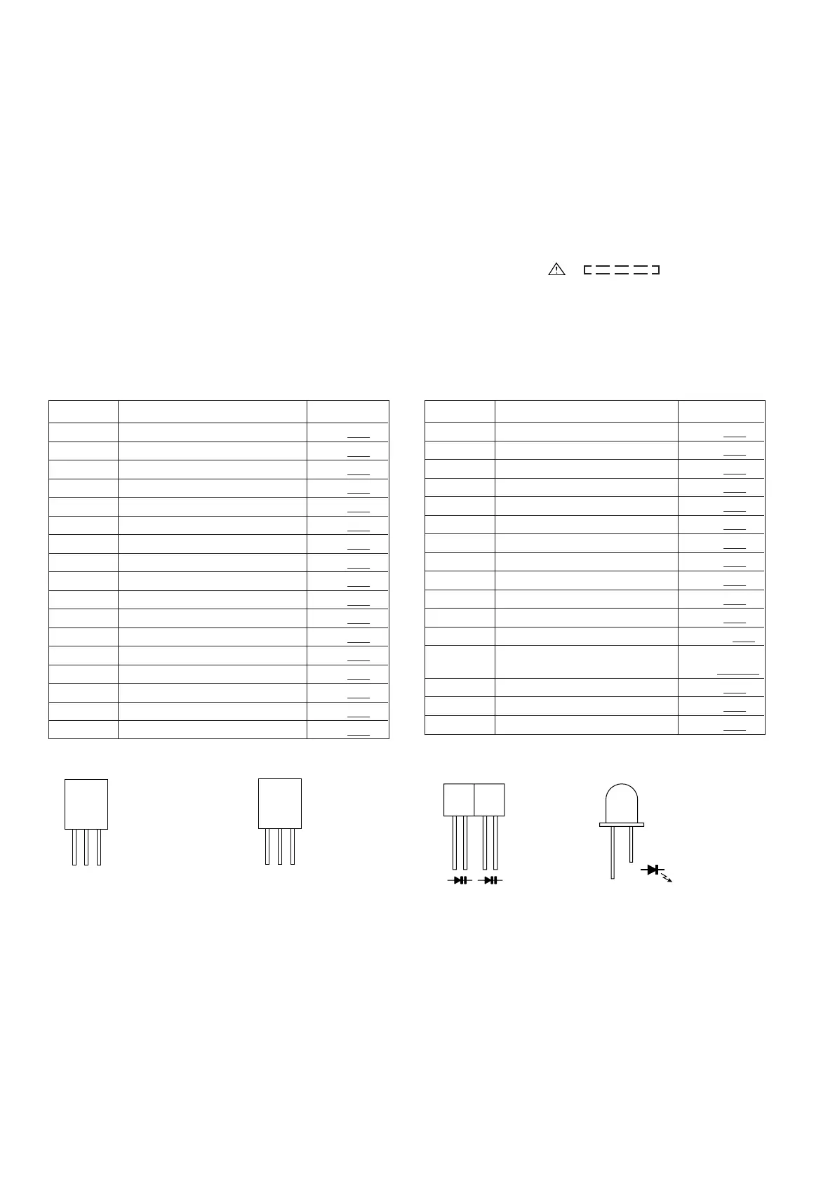
Figure 12 TYPES OF TRANSISTOR AND LED
KRC102 M
KRC104 M
KRC107 M
KTA1266 GR
KTA1271 Y
KTC3199 GR
KTC3203 Y
2SK246 GR
KTA1273 Y
KTC3200 GR
E
(1)
(S)
C
(2)
(G)
B
(3)
(D)
FRONT
VIEW
B
(3)
C
(2)
E
(1)
FRONT
VIEW
KV1236Z23F
FRONT
VIEW
333GTH2