EasyManua.ls Logo

Sharp CD-C2800 User Manual

Sharp CD-C2800
56 pages
To Next Page IconTo Next Page
Page #1 background imageLoading...
Page #1 background image
– 1 –
CD-C422/C422C/C2800/C2800C
No. S3820CDC422//
Illustration: CD-C422/C422C
Illustration: CD-C2800/C2800C
CONTENTS
Page
IMPORTANT SERVICE NOTES (For U.S.A. Only) .......................................................................................................... 2
SPECIFICATIONS .............................................................................................................................................................2
NAMES OF PARTS .......................................................................................................................................................... 3
OPERATION MANUAL..................................................................................................................................................... 5
QUICK GUIDE .................................................................................................................................................................. 6
DISASSEMBLY................................................................................................................................................................. 7
REMOVING AND REINSTALLING THE MAIN PARTS.................................................................................................. 10
ADJUSTMENT................................................................................................................................................................ 11
NOTES ON SCHEMATIC DIAGRAM ............................................................................................................................. 13
WAVEFORMS OF CD CIRCUIT..................................................................................................................................... 14
BLOCK DIAGRAM .......................................................................................................................................................... 15
SCHEMATIC DIAGRAM / WIRING SIDE OF P.W.BOARD.............................................................................................18
TROUBLESHOOTING (CD CHANGER CONTROL / CD SECTION)............................................................................. 32
FUNCTION TABLE OF IC .............................................................................................................................................. 36
FL DISPLAY.................................................................................................................................................................... 42
REPLACEMENT PARTS LIST/EXPLODED VIEW
PACKING OF THE SET (For U.S.A. Only)
CD-C422/C422C
CP-C422, REAR SPEAKER SYSTEM,
Constitute CD-C422/C422C.
CD-C2800/C2800C
CP-C2800, REAR SPEAKER SYSTEM,
Constitute CD-C2800/C2800C.
In the interests of user-safety the set should be restored to its
original condition and only parts identical to those specified be
used.
SERVICE MANUAL
This document has been published to be used
for after sales service only.
The contents are subject to change without notice.
SHARP CORPORATION
Question and Answer IconNeed help?

Do you have a question about the Sharp CD-C2800 and is the answer not in the manual?

Sharp CD-C2800 Specifications

General IconGeneral
TypeStereo System
CD PlayerYes
FM RadioYes
BluetoothNo
USB PortNo
Disc Capacity1
Playable MediaCD, CD-R, CD-RW
RadioFM
Cassette DeckNo
Speakers2

Summary

Important Service Notes

Specifications

General Specifications

General specifications including power, dimensions, and weight.

Amplifier Section Specifications

Details on amplifier output power and impedance.

Tuner Section Specifications

Frequency range and signal characteristics for FM/AM tuning.

Cassette Deck Section Specifications

Specifications for cassette playback and recording.

Compact Disc Player Section Specifications

Details on CD player type, signal readout, and converter.

Front Speaker Section Specifications

Specifications for front speaker types, power, and dimensions.

Rear Speaker Section Specifications

Specifications for rear speaker types, power, and dimensions.

Names of Parts

Front Panel Components

Identifies controls and indicators on the front panel.

Rear Panel Connections

Identifies input/output sockets on the rear panel.

Remote Control Functions

CD Control Section

Describes remote control buttons for CD operations.

Tuner Control Section

Describes remote control buttons for tuner operations.

Tape Control Section

Describes remote control buttons for tape operations.

Operation Manual

Setting the Clock

Step-by-step guide to setting the unit's clock time.

Resetting the Microcomputer

Instructions for resetting the system microcomputer.

Quick Guide

Preparation for Use

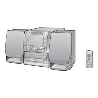
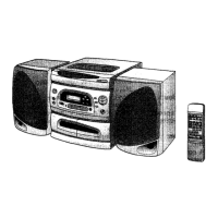
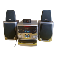
Initial setup and connection guide for the audio system.

Basic Operations

Summarizes key operations like tape playback, CD playback, radio, and recording.

Disassembly

Disassembly Precautions

Guidelines for safe and effective unit disassembly.

Top Cabinet Disassembly

Procedure for removing the top cabinet.

Side Panel Disassembly

Procedure for removing side panels.

CD Player Unit Disassembly

Steps to remove the CD player unit and tray cover.

Back Board Disassembly

Procedure for removing the back board.

PWB Removal

Steps for removing switch, display, and main PWBs.

Front Panel Disassembly

Procedure for removing the front panel.

Tape Mechanism Disassembly

Steps to remove the tape mechanism.

Turntable and Disc Tray Removal

Procedures for removing turntable and disc tray.

CD Mechanism Disassembly

Steps to remove CD changer and CD mechanisms.

Manual CD Changer Operation

Instructions for manually opening the CD changer.

Removing and Reinstalling Main Parts

CD Mechanism Section

Procedures for removing and reinstalling CD mechanism components.

Loading Motor Removal

Steps to remove the CD loading motor.

Pickup Removal

Steps to remove the CD pickup assembly.

Adjustment

Mechanism Section Adjustments

Adjustments for tape mechanism driving force, torque, and speed.

Driving Force Check

Procedure to check tape mechanism driving force.

Torque Check

Procedure to check tape mechanism torque.

Tape Speed Adjustment

Procedure to check tape speed.

Tuner Section Adjustments

Adjustments for AM/FM RF, IF, and VCO frequency.

AM IF/RF Adjustment

Steps for adjusting AM Intermediate and Radio Frequency stages.

FM RF Adjustment

Steps for adjusting FM Radio Frequency stage.

Detection Adjustment

Procedure for adjusting the detection stage.

VCO Frequency Adjustment

Procedure for adjusting the Voltage Controlled Oscillator frequency.

Test Mode Operations

Setting the Test Mode

Steps to enter various test modes.

CD Test Mode Function

Details on the CD test mode operation.

CD Section Adjustments

Automatic Adjustment Items

Explanation of automatic adjustment functions.

Schematic Diagram Notes

Component Symbol Explanations

Explains symbols for resistors and capacitors used in diagrams.

Voltage Measurement and Safety Notes

Guidelines for voltage measurements and identifying safety-critical parts.

Switch and Transistor Identification

Lists switches and transistors with their functions and types.

Waveforms of CD Circuit

Block Diagram (1/3)

Block Diagram (2/3)

Block Diagram (3/3)

Wiring Side of P.W.Board (1/4)

Wiring Side of P.W.Board (2/4)

Wiring Side of P.W.Board (3/4)

Wiring Side of P.W.Board (4/4)

Schematic Diagram (1/10)

Schematic Diagram (2/10)

Schematic Diagram (3/10)

Schematic Diagram (4/10)

Schematic Diagram (5/10)

Schematic Diagram (6/10)

Schematic Diagram (7/10)

Schematic Diagram (8/10)

Schematic Diagram (9/10)

Schematic Diagram (10/10)

CD Section Troubleshooting

CD Section Not Functioning

Steps to diagnose issues when the CD section does not operate.

Turntable Stop Failure

Troubleshooting steps for when the turntable fails to stop.

Turntable Movement Failure

Steps to resolve issues with turntable movement.

CD Troubleshooting Continued

CD Tray Open/Close Failure

Diagnosing problems with the CD tray operation.

CD Functionality Issues

Troubleshooting steps for non-working CD functions and keys.

CD Playback Without Disc

Checks for playback operation without a disc and pickup movement.

CD Playback Troubleshooting

Disc Loading Playback Issues

Diagnosing playback problems requiring a loaded disc.

Focus Servo and Signal Checks

Verifying focus servo activity and signal levels (DRF, HF).

Tracking System Checks

Steps to troubleshoot tracking servo and data read errors.

CD System Diagnostics

Spin System Check

Verifying turntable rotation and spin driver circuit.

VCO-PLL System Check

Troubleshooting VCO-PLL system and TOC data reading.

No Sound Emission Issue

Diagnosing no sound problems with normal waveforms and time.

Integrated Circuit Function Tables

IC2 Servo/Signal Control Pinout (Part 1)

Detailed pin functions for IC2 (LC78623D), first part.

IC2 Servo/Signal Control Pinout (Part 2)

IC2 Servo/Signal Control Block Diagram

IC1 Servo Amplifier Pinout

IC1 Servo Amplifier Pinout (Part 1)

Detailed pin functions for IC1 (LA9241M), first part.

IC1 Servo Amplifier Pinout (Part 2)

IC1 Servo Amplifier Block Diagram

IC701 Microcomputer Pinout

IC701 Microcomputer Pinout (Part 1)

Detailed pin functions for IC701 (IX0191AW), first part.

IC701 Microcomputer Pinout (Part 2)

IC701 Microcomputer Block Diagram

IC5 Driver and FL Display

IC5 Driver IC Block Diagram

Block diagram for IC5 (M56748FP) driver functions.

FL Display Indicators

Visual representation of the FL display indicators and their meanings.

Parts Ordering Information

Ordering Replacement Parts

Procedures for ordering replacement parts with required information.

Component Code Explanations

Guide to understanding capacitor and resistor part code notations.

Parts List - Integrated Circuits

Integrated Circuits (ICs)

List and specifications for integrated circuits used in the unit.

Parts List - Discrete Components

Transistors and Diodes

List of transistors and diodes with part codes and descriptions.

Filters, Transformers, Coils

List of filters, transformers, and coils with part codes.

Resistors and Capacitors

Comprehensive list of resistors and capacitors with part codes.

Resistors (Continued)

Capacitors (Continued)

Resistors (Continued)

Assembly Parts Lists

Circuitry and Mechanism Parts

Lists connectors, switches, and CD mechanism components.

Cabinet and Speaker Components

Lists cabinet parts and speaker assembly components.

Speaker Box Parts

Speaker Box Parts

Lists parts for front and rear speaker assemblies.

Accessories and PWB Assemblies

Lists accessories and printed wiring board assemblies.

CD Mechanism Exploded View

Cabinet Exploded View (1/2)

Cabinet Exploded View (2/2)

Speaker Exploded View (1/3)

Speaker Exploded View (2/3)

Speaker Exploded View (3/3)

Packing Instructions (USA)

Switch and Knob Settings for Packing

Specifies positions for switches and knobs before packing.

Packing Details for Main Unit and Speakers

Instructions for packing the main unit, rear speakers, and front speakers.

Related product manuals