– 11 –
CD-C612
• AM IF/RF
Signal generator: 400 Hz, 30%, AM modulated
*1. Input: Antenna, Output: TP302
*2. Input: Antenna, Output: TP301
TUNER SECTION
fL: Low-range frequency
fH: High-renge frequency
IF 450 kHz 1,720 kHz T351 *1
Band — 530 kHz (fL): T333 *2
Coverage 1.1 ± 0.1 V
Tracking 990 kHz 990 kHz (fL): T331 *1
Test Stage
Frequency Frequency
Display
Setting/
Adjusting
Parts
Instrument
Connection
*1. Input: Antenna, Output: TP301
*2. Input: Antenna, Output: Speaker terminal
• FM RF
Signal generator: 1 kHz, 75 kHz dev., FM modulated
Band — 87.50 MHz L303(fL): *1
Coverage 3.4 V ± 50 mV
RF 98.00 MHz 98.00 MHz L302 *2
(10-30 dB)
Test Stage
Instrument
Connection
Frequency
Frequency
Display
Serring/
Adjusting
Point
• Detection
Signal generator: 10.7 MHz, FM sweep generator
Detection 10.7 MHz 98.00 MHz T352 Input: Pin 1 of
IC303
Output: TP302
IF 10.7 MHz 98.00 MHz T301(Turn Input: Pin 1 of
the core of IC301
transformer Output: TP302
T352 fully
counter-
clookwise.)
Instrument
Connection
Test
Stage
Adjusting
Parts
Frequency
Display
Frequency
Adjusting
Parts
Instrument
Connection
Frequency
Display
Frequency
• VCO Frequency
* Adjust for 76 kHz ± 200 Hz.
Notes:
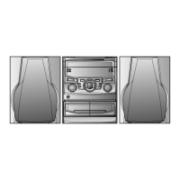
After preparing the test circuit shown in Fig 11-2, connect the
Pin 13 , Pin 21 and ground of the IC303 with test circuit, and
measure the Value.
At this time, apply a standard unmodulated signal input and
adjust the VCO.
Figure 11-2
98.00 MHz 98.00 MHz VR351* Pin 13, Pin 21
(60 dB) and ground
of IC303
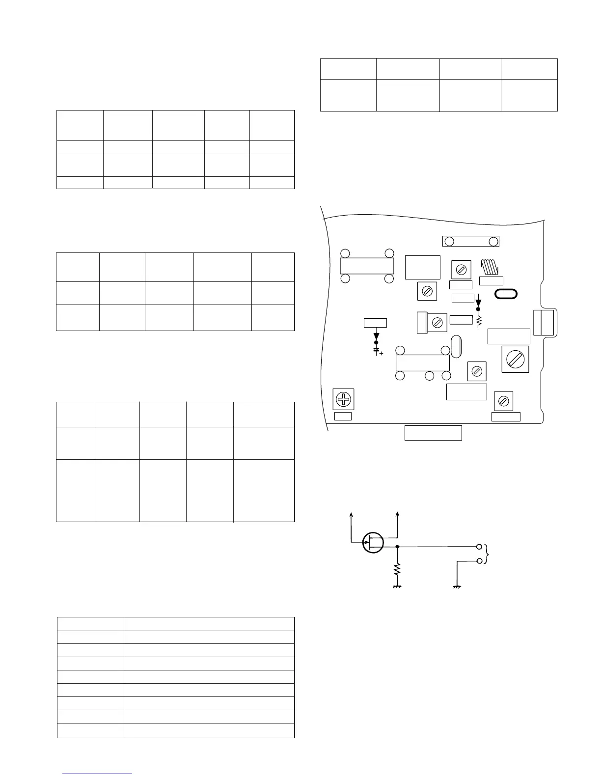
Figure 11-1 ADJUSTMENT POINTS
Pin 13 of IC303
Pin 21 of IC303
D
G
S
10 kΩ
TO FREQUENCY
COUNTER
FET : 2SK19 or 2SK54
MAIN PWB
CNP301
FM Band
Coverage
fL
TP301
VCO
AM IF
FM RF
FM DET
FM IF
AM Tracking
fL
AM Band
Coverage fL
TP302
IC302
T331
T352
CF351
T351
CF301
IC303
C356
R361
T333
VR351
L303
IC301
T301
L302
BF301
1
11
12
22
1
12
13
21
24
1
9
CD ERROR CODE DESCRIPTION
When a malfunction occurs during CD operation, an error
code will be displayed to identify the function in CD operation
which failed.
Error State Code
0001 Cannot detect puin SW
0101 Tray close operation error
0105 Tray close operation error
0201 Tray open operation error
0203 Tray open operation error
0304 Disc skip operation error
0305 Disc skip operation error
0307 Disc skip operation error