Home
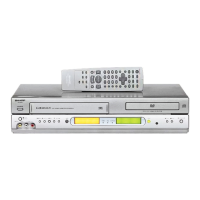
Sharp
DVD VCR Combo
DV-NC65H
Service Manual
Page 42
Sharp DV-NC65H - Page 42
113 pages
Manual
Save Page as PDF
To Next Page
To Next Page
To Previous Page
To Previous Page
Loading...
42
DV-NC65H/S
DV-NC70H
Figure 8-45.
LANGF9661AJFW
Top surface should be free from scratches or soil.
When assemble drive lever to frame R (on the
back side), make sure the hole synchronize.
4.
Frame R, Frame L, Drive Arm R, Drive Arm L, Upper Plate.
41
43
Table of Contents
Main Page
Table of Contents
1
Important Service Notes
2
Features
3
Specifications
3
Part Names
5
Maintenance Check Items and Execution Time
14
Disassembly Method
15
Operation of Pickup
19
Adjustment, Replacement and Assembly of Mechanical Units
20
Test Mode
43
Block Diagrams
64
Schematic Diagrams
69
Printed Wiring Board Assemblies
92
Replacement Parts List
92
Packing of the Set
111
Other manuals for Sharp DV-NC65H
Operation Manual
102 pages
Related product manuals
Sharp DV-NC60W
109 pages
Sharp DV-NC70
99 pages
Sharp DV-NC80W
110 pages
Sharp DV-NC100
32 pages
Sharp DV-NC55S
135 pages
Sharp DV-RW550U
112 pages
Sharp DV-RW260H
4 pages
Sharp DV-RW340U
112 pages