LC-37D90U
5 – 54
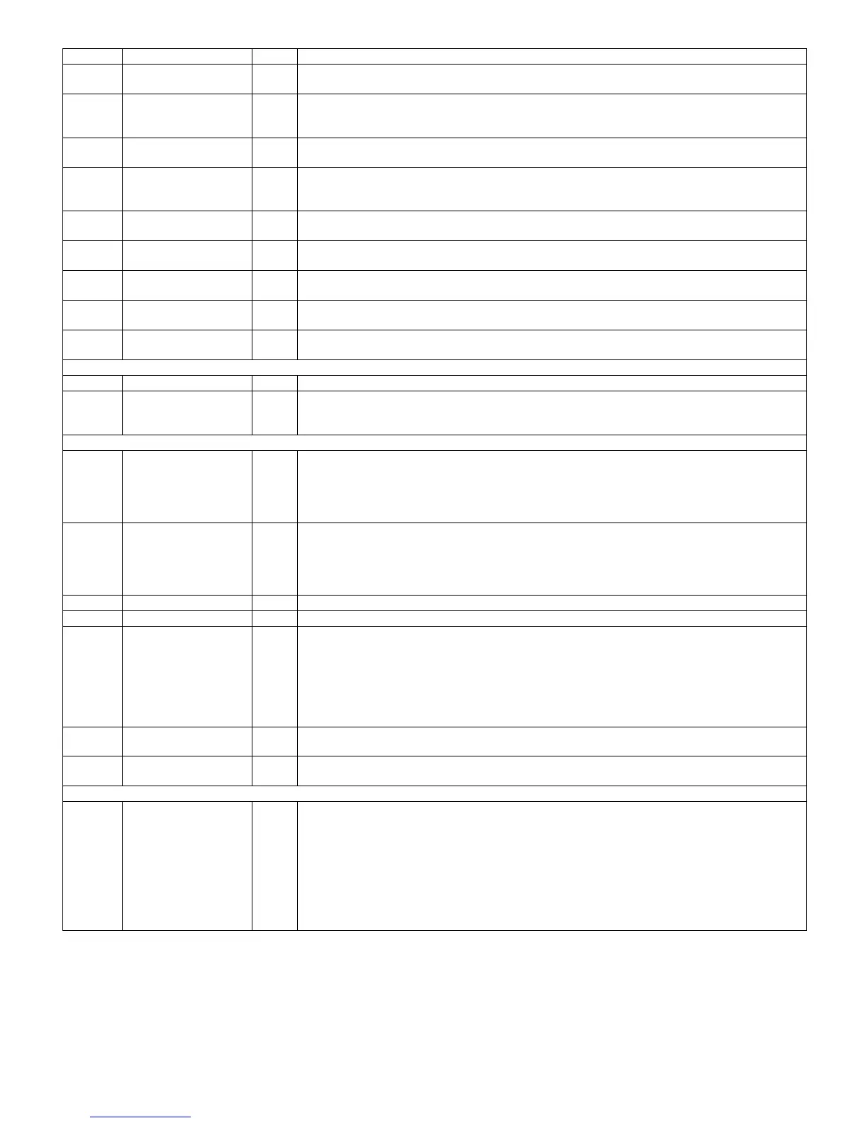
M13 GPIO2 I/O GPIO. Output is controlled by the internal register. Input is monitored by internal register.
Can be used as watermark for also buffer 1.
N14 GPIO3 I/O GPIO. Output is controlled by the internal register. Input is monitored by internal register.
For HSDI1 RX mode 8/9 (ceLynx Sync mode B compatible), it can be configured for HSDI1 AV out-
put.
M14 GPIO4 I/O GPIO. Output is controlled by the internal register. Input is monitored by internal register.
Can be used as watermark for also buffer 2.
B11 GPIO5 I/O GPIO. Output is controlled by the internal register. Input is monitored by internal register.
For HSDI2 RX mode 8/9 (ceLynx Sync mode B compatible), it can be configured for HSDI2 AV out-
put.
A10 GPIO6 I/O GPIO. Output is controlled by the internal register. Input is monitored by internal register.
Can be used as watermark for any Async buffer.
A11 GPIO7 I/O GPIO. Output is controlled by the internal register. Input is monitored by internal register.
Can be used as watermark for any Async buffer.
E10 GPIO8 I/O GPIO. Output is controlled by the internal register. Input is monitored by internal register.
Can be used as watermark for any Async buffer.
B9 GPIO9 I/O GPIO. Output is controlled by the internal register. Input is monitored by internal register.
Can be used as watermark for any Async buffer.
C7 GPIO10 I/O GPIO. Output is controlled by the internal register. Input is monitored by internal register.
Can be used as watermark for any Async buffer.
Test Modes
D9 TEST_MODE I Used for internal TI testing. Should be tied to GND for normal operation.
A2, A4,
C2, C3,
D3
NO_CONNECT --- These pins should not be connected to any signal, power, or ground.
Power and Ground Signals
F3, J5,
L2, K5,
M9, P14,
K11,
C14, B8
VDD3.3 --- 3.3V power supply for I/O power.
E3, E4,
N2, N3,
M12,
N13,
C13, C12
VDD1.5 --- 1.5V power supply for core power.
D1 PLLVDD1.5 --- 1.5V power supply for PHY PLL.
C1 PLLVSS --- PLL ground.
G5, L4,
N4, M7,
P11,
K13,
H14,
F13,
B12, C10
VSS --- Ground.
D2, D7,
C6, A5
AVdd3.3 --- Analog VDD.
D6, B5,
D4, B2
AVSS --- Analog Ground.
Thermal Balls
E5, J6,
J7, J8,
J9, H6,
H7, H8,
H9, G6,
G7, G8,
G9, F6,
F7, F8,
F9
--- --- The center device balls are connected together, but electrically isolated from the device. For thermal
purposes, its recommended to connect these balls to a thermal dissipating ground plane (e.g. Vss).
Pin No. Pin Name I/O Pin Function