LC-40/46/52/60Z5T
1 – 4
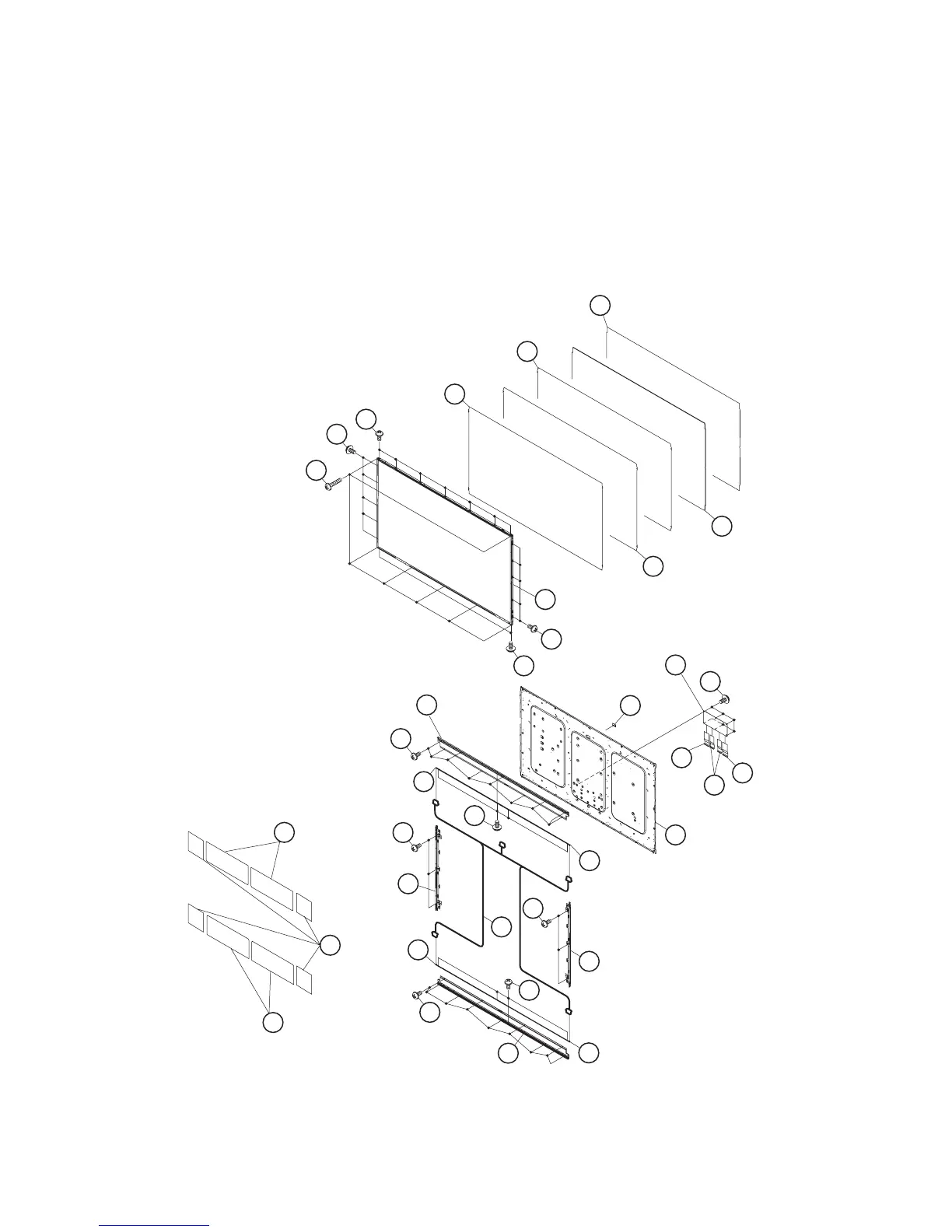
[4] LC-60Z5T
1. Remove the 7 lock screws [1], 19 lock screws [2] and detach the 60” LCD Panel HIRAKI Unit [3].
2. Detach the DBEF Sheet [4], Lens Sheet [5], Micro Lens Sheet [6], Light Guide Plate [7], Reflection Sheet [8], 4 pieces Graphite Sheet [9] and 4
pieces Graphite Sheet [23].
3. Remove the 18 lock screws [10] and detach the 2 pieces LED Angle [11].
4. Remove the 8 lock screws [12] and detach the 4 pieces LED-PWB [13].
5. Remove the 6 lock screws [14] and detach the 2 pieces Holder Unit [15].
6. Detach the LED Cable Cover (Cap) [16].
7. Disconnect the LED cable [17].
8. Remove the 6 lock screws [18] and disconnect the 2 pieces FFC (80Pin) [19], FFC (64Pin)[20] and detach the C-PWB [21] .
9. Detach the and Back Light Chassis Unit [22].
5 Lens Sheet
7
Light Guide Plate
4DBEF Sheet
6Micro Lens Sheet
8Reflection Sheet
3 60" LCD Panel HIRAKI Unit
2
2
2
2
1
21
16
C-PWB
20
19
19
FFC
(64Pin)
FFC
(80Pin)
FFC
(80Pin)
22
10
11
LED Angle
LED Angle
12
13LED-PWB
LED-PWB
LED-PWB
LED-PWB
13
12
14
15 Holder Unit
14
15Holder Unit
17
13
13
11
10
18
9
Graphite Sheet
9
Graphite Sheet
23
Graphite Sheet
LED Cable Cover (Cap)
Back Light
Chassis Unit