EasyManua.ls Logo

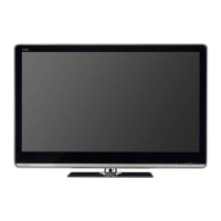
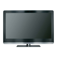
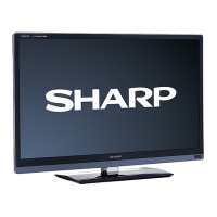
Sharp LC-40LE820E

Sharp LC-40LE820E
158 pages
To Next Page IconTo Next Page
Loading...
SERVICE MANUAL
Parts marked with " " are important for maintaining the safety of the set. Be sure to replace these parts with specified ones for maintaining the
safety and performance of the set.
This document has been published to be used for
after sales service only.
The contents are subject to change without notice.
SAFETY PRECAUTION
IMPORTANT SERVICE SAFETY PRE-
CAUTION ............................................................i
Precautions for using lead-free solder ...............ii
End of life disposal ............................................ iii
OUTLINE
MAJOR SERVICE PARTS ................................iv
CHAPTER 1. SPECIFICATIONS
[1] SPECIFICATIONS ......................................... 1-1
CHAPTER 2. OPERATION MANUAL
[1] OPERATION MANUAL .................................. 2-1
CHAPTER 3. DIMENSIONS
[1] DIMENSIONS (LC-40LE820E/LU820E)........ 3-1
[2] DIMENSIONS (LC-46LE820E/LU820E)........ 3-2
[3] DIMENSIONS (LC-52LE820E) ...................... 3-3
CHAPTER 4. REMOVING OF MAJOR PARTS
[1] REMOVING OF MAJOR PARTS
(LC-40LE820E/LU820E) ................................ 4-1
[2] REMOVING OF MAJOR PARTS
(LC-46LE820E/LU820E) ................................ 4-6
[3] REMOVING OF MAJOR PARTS
(LC-52LE820E) ............................................ 4-11
[4] Caution Cleaning Glass ............................... 4-16
[5] How to replace the touch key sensor
PWB ............................................................. 4-18
CHAPTER 5. Enter the chapter title here.
[1] LC-40LE820E/LU820E ..................................5-1
[2] LC-46LE820E/LU820E ..................................5-2
[3] LC-52LE820E ................................................5-3
CHAPTER 6. ADJUSTMENT
[1] ADJUSTMENT PROCEDURE ......................6-1
CHAPTER 7. TROUBLESHOOTING TABLE
[1] TROUBLESHOOTING TABLE ......................7-1
[2] LED flashing specification at the time of the
error .............................................................7-13
CHAPTER 8. MAJOR IC INFORMATIONS
[1] MAJOR IC INFORMATIONS .........................8-1
CHAPTER 9. OVERALL WIRING/BLOCK DIAGRAM
[1] OVERALL WIRING
(LC-40LE820E/LU820E)................................9-1
[2] OVERALL WIRING
(LC-46LE820E/LU820E)................................9-2
[3] OVERALL WIRING (LC-52LE820E)..............9-3
[4] SYSTEM BLOCK DIAGRAM.........................9-4
Parts Guide
TopPage
CONTENTS
In the interests of user-safety (Required by safety regulations in some countries) the set should be restored to its orig-
inal condition and only parts identical to those specified should be used.
LC-40/46/52LE820E, LC-40/46LU820E
LCD COLOUR TELEVISION
No. S30F240LE820E
LC-40LE820E
LC-46LE820E
LC-52LE820E
LC-40LU820E
LC-46LU820E
MODELS

Table of Contents

Other manuals for Sharp LC-40LE820E

Question and Answer IconNeed help?

Do you have a question about the Sharp LC-40LE820E and is the answer not in the manual?

Sharp LC-40LE820E Specifications

General IconGeneral
BrandSharp
ModelLC-40LE820E
CategoryLCD TV
LanguageEnglish

Summary

Safety Precautions and Disposal

Important Service Safety Precautions

Crucial safety guidelines for technicians performing service.

Lead-Free Solder Precautions

Guidelines for handling and using lead-free solder during repairs.

End of Life Disposal Information

Instructions for environmentally sound disposal of the product.

Outline and Major Service Parts

Major Service Parts Identification

List of primary components identified as major service parts.

Chapter 1: Product Specifications

Detailed Specifications

Technical specifications for the LCD Colour Television models.

Chapter 2: Operation Manual

Operation Overview and Controls

Instructions on using the TV's functions and identifying controls.

Chapter 3: Product Dimensions

Dimensions for 40-inch Models

Physical dimensions for LC-40LE820E/LU820E.

Dimensions for 46-inch Models

Physical dimensions for LC-46LE820E/LU820E.

Dimensions for 52-inch Model

Physical dimensions for LC-52LE820E.

Chapter 4: Major Parts Removal Procedures

Removing Parts for 40-inch Models

Step-by-step guide to removing major components for specific models.

Removing Parts for 46-inch Models

Step-by-step guide to removing major components for specific models.

Removing Parts for 52-inch Model

Step-by-step guide to removing major components for specific models.

Cautionary Glass Cleaning

Safety and handling procedures for cleaning glass components.

Touch Key Sensor PWB Replacement

Instructions for replacing the touch key sensor PWB.

Chapter 5: Touch Sensor Unit Details

Touch Sensor Unit Dimensions (40-inch)

Dimensional information for the touch sensor unit on 40-inch models.

Touch Sensor Unit Dimensions (46-inch)

Dimensional information for the touch sensor unit on 46-inch models.

Touch Sensor Unit Dimensions (52-inch)

Dimensional information for the touch sensor unit on 52-inch models.

Chapter 6: Service Adjustments

Adjustment Procedure Overview

General steps for performing adjustments after part replacement.

Entering and Exiting Adjustment Mode

Guide to accessing and leaving the service adjustment mode.

Lamp Error Detection and Reset

Procedure for managing lamp error detection and resetting counts.

Video Signal Adjustment

Steps for adjusting video signals via the adjustment process menu.

White Balance Adjustment

Procedure for adjusting the white balance of the display.

Initialization to Factory Settings

Steps to reset the TV to its original factory settings.

Software Upgrade Procedure

Instructions for updating the TV's software via USB.

Chapter 7: Troubleshooting Guide

No PowerNo Startup Troubleshooting

Steps to diagnose and resolve power-on issues.

No Sound Troubleshooting

Diagnostic flowcharts for troubleshooting audio output problems.

No Picture Troubleshooting

Steps to diagnose and resolve display issues across various inputs.

LED Flashing Specifications

Interpretation of LED blinking patterns indicating error conditions.

Chapter 8: Major IC Information

Key Integrated Circuits and Functions

Details on major ICs used in the main unit and their functions.

Chapter 9: Wiring and Block Diagrams

Overall Wiring Diagrams

Visual representation of component interconnections for different models.

System Block Diagram

High-level overview of the TV's internal system architecture.

Parts Guide

Printed Wiring Board Assemblies

List of PWB assemblies and their part codes.

LCD Panel Modules

Specific LCD panel units for different model sizes.

Cabinet Parts (4046-inch)

List of external and internal cabinet components by model.

Cabinet Parts (52-inch)

List of external and internal cabinet components by model.

Supplied Accessories

List of items included with the TV unit.

Packing Parts (4046-inch)

Details of packaging materials used for shipping.

Packing Parts (52-inch)

Details of packaging materials used for shipping.

Service Jigs

Tools recommended for servicing procedures.

Service Manual Overview

Chapter 1: Printed Wiring Board Assemblies

Introduction to the PWB assembly documentation.

Chapter 2: Schematic Diagram

Introduction to the schematic diagram documentation.

Parts Guide Reference

Reference to the detailed parts guide.

LCD Module Handling and Removal

Chapter 1: Removing LCD Module

Step-by-step instructions for removing the LCD module assembly.

Chapter 2: Handling Notes LCD Module

Important precautions for handling the LCD module during service.

LCD Panel Module Parts Lists

Parts for 40-inch LCD Panel Module

Detailed list of parts for the 40-inch LCD panel module.

Parts for 46-inch LCD Panel Module

Detailed list of parts for the 46-inch LCD panel module.

Parts for 52-inch LCD Panel Module

Detailed list of parts for the 52-inch LCD panel module.
Related product manuals