EasyManua.ls Logo

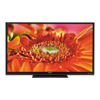
Sharp LC-80LE642U User Manual

Sharp LC-80LE642U
78 pages
To Next Page IconTo Next Page
Page #1 background imageLoading...
Page #1 background image
SERVICE MANUAL
Parts marked with " " are important for maintaining the safety of the set. Be sure to replace these parts with specified ones for maintaining the
safety and performance of the set.
This document has been published to be used for
after sales service only.
The contents are subject to change without notice.
SAFETY PRECAUTION
IMPORTANT SERVICE SAFETY PRE-
CAUTION ............................................................i
PRECAUTIONS A PRENDRE LORS DE
LA REPARATION ...............................................ii
PRECAUTIONS FOR USING LEAD-FREE
SOLDER ........................................................... iii
OUTLINE
MAJOR SERVICE PARTS ................................iv
CHAPTER 1. SPECIFICATIONS
[1] SPECIFICATIONS ......................................... 1-1
CHAPTER 2. OPERATION MANUAL
[1] OPERATION MANUAL .................................. 2-1
CHAPTER 3. DIMENSIONS
[1] DIMENSIONS ................................................ 3-1
CHAPTER 4. REMOVING OF MAJOR PARTS
[1] REMOVING OF MAJOR PARTS ................... 4-1
[2] The location putting on the heat measure
sheet .............................................................. 4-9
[3] Precautions for assembly............................. 4-10
CHAPTER 5. ADJUSTMENT
[1] ADJUSTMENT PROCEDURE ......................5-1
[2] PUBLIC MODE SETTING PROCEDURE......5-15
CHAPTER 6. TROUBLESHOOTING TABLE
[1] Failure diagnosis by LED in front of cabinet........6-1
[2] LED flashing specification at the time of an
error (Center icon LED used) ........................6-1
[3] TROUBLESHOOTING TABLE ......................6-4
CHAPTER 7. MAJOR IC INFORMATIONS
[1] MAJOR IC INFORMATIONS .........................7-1
CHAPTER 8. OVERALL WIRING/SYSTEM BLOCK
DIAGRAM
[1] OVERALL WIRING DIAGRAM......................8-1
[2] SYSTEM BLOCK DIAGRAM .........................8-2
Parts Guide
TopPage
CONTENTS
No. S73B9LC80LE64
LCD COLOR TELEVISION
LC-80LE642U
MODEL
In the interests of user-safety (Required by safety regulations in some countries) the set should be restored to its orig-
inal condition and only parts identical to those specified should be used.
LC-80LE642U
Question and Answer IconNeed help?

Do you have a question about the Sharp LC-80LE642U and is the answer not in the manual?

Sharp LC-80LE642U Specifications

General IconGeneral
Screen shapeFlat
Response time- ms
Display diagonal80 \
Display brightness- cd/m²
Native aspect ratio16:9
Native refresh rate120 Hz
LED backlighting typeFull-Array
Contrast ratio (dynamic)400000:1
3D-
Audio input4
Analog signal format systemNTSC
Digital signal format systemATSC
RMS rated power20 W
Number of speakers2
DVI portNo
DVI-D ports quantity0
USB 2.0 ports quantityUSB 2.0 ports have a data transmission speed of 480 Mbps, and are backwards compatible with USB 1.1 ports. You can connect all kinds of peripheral devices to them.
Wi-Fi standards802.11a, 802.11b, 802.11g
Product colorBlack
Panel mounting interface600 x 400 mm
AC input voltage120 V
AC input frequency60 Hz
Power consumption (standby)- W
Package depth312.7 mm
Package width2035.9 mm
Package height1247.7 mm
Package weight69490 g
Sustainability certificatesENERGY STAR
Weight and Dimensions IconWeight and Dimensions
Depth (with stand)434.1 mm
Height (with stand)1145.3 mm
Weight (with stand)59511 g
Depth (without stand)99.2 mm
Width (without stand)1862.1 mm
Height (without stand)1112 mm
Weight (without stand)55519 g

Summary

CHAPTER 1. SPECIFICATIONS

[1] SPECIFICATIONS

Detailed technical specifications of the TV set, including panel, inputs, and power requirements.

CHAPTER 2. OPERATION MANUAL

[1] OPERATION MANUAL

Instructions for operating the TV set, including part names and button functions.

CHAPTER 3. DIMENSIONS

[1] DIMENSIONS

Provides dimensional drawings of the TV set with measurements in inches and millimeters.

CHAPTER 4. REMOVING OF MAJOR PARTS

[1] REMOVING OF MAJOR PARTS

Step-by-step instructions for removing the stand unit and rear cabinet assembly.

[2] The location putting on the heat measure sheet

Identifies the specific location for placing heat measure sheets on the main PWB unit.

[3] Precautions for assembly

Important points and precautions to follow during the assembly process.

CHAPTER 5. ADJUSTMENT

[1] ADJUSTMENT PROCEDURE

Details the procedure for adjusting settings after PWB or IC replacement.

CHAPTER 6. TROUBLESHOOTING TABLE

[1] Failure diagnosis by LED in front of cabinet

Guide for diagnosing failures based on the status of the front cabinet LED.

[2] LED flashing specification at the time of an error (Center icon LED used)

Details LED flashing patterns for error identification.

[3] TROUBLESHOOTING TABLE

A comprehensive table outlining troubleshooting steps for various issues.

CHAPTER 7. MAJOR IC INFORMATIONS

[1] MAJOR IC INFORMATIONS

Provides technical information on key integrated circuits used in the system.

CHAPTER 8. OVERALL WIRING/SYSTEM BLOCK DIAGRAM

[1] OVERALL WIRING DIAGRAM

Diagram illustrating the overall wiring connections of the unit.

[2] SYSTEM BLOCK DIAGRAM

Block diagram showing the system architecture and component interactions.

[1] PRINTED WIRING BOARD ASSEMBLIES

[2] LCD PANEL MODULE UNIT

[3] CABINET AND MECHANICAL PARTS

[4] SUPPLIED ACCESSORIES/PACKING PARTS

[5] SERVICE JIG (USE FOR SERVICING)

Related product manuals