MD-MS200W/MD-MS200/MD-MS200H
– 11 –
Step 1 Test mode STOP state [ T E S T ]
Step 2 BASS button
Step 3 AUTO menu [ A U T O ]
Step 4 SKIP UP button x 2 times
(Or SKIP DOWN button x 8 times)
Step 5 RESULT menu [ R E S U L T ]
Step 6 PLAY button
Step 7 Indication of measurement value: [ T E O : ]
Tracking error offset
Step 8 SKIP UP button
Step 9 Indication of measurement value: [ F E O : ]
Focus error offset
Step 10 SKIP UP button
Step 11 Indication of measurement value: [ H f _ _ ]
High reflection focus gain
Step 12 SKIP UP button
Step 13 Indication of measurement value: [ H g _ _ ]
High reflection pit tracking gain
Step 14 SKIP UP button
Step 15 Indication of measurement value: [ H b _ _ ]
High reflection pit tracking balance
Step 16 SKIP UP button
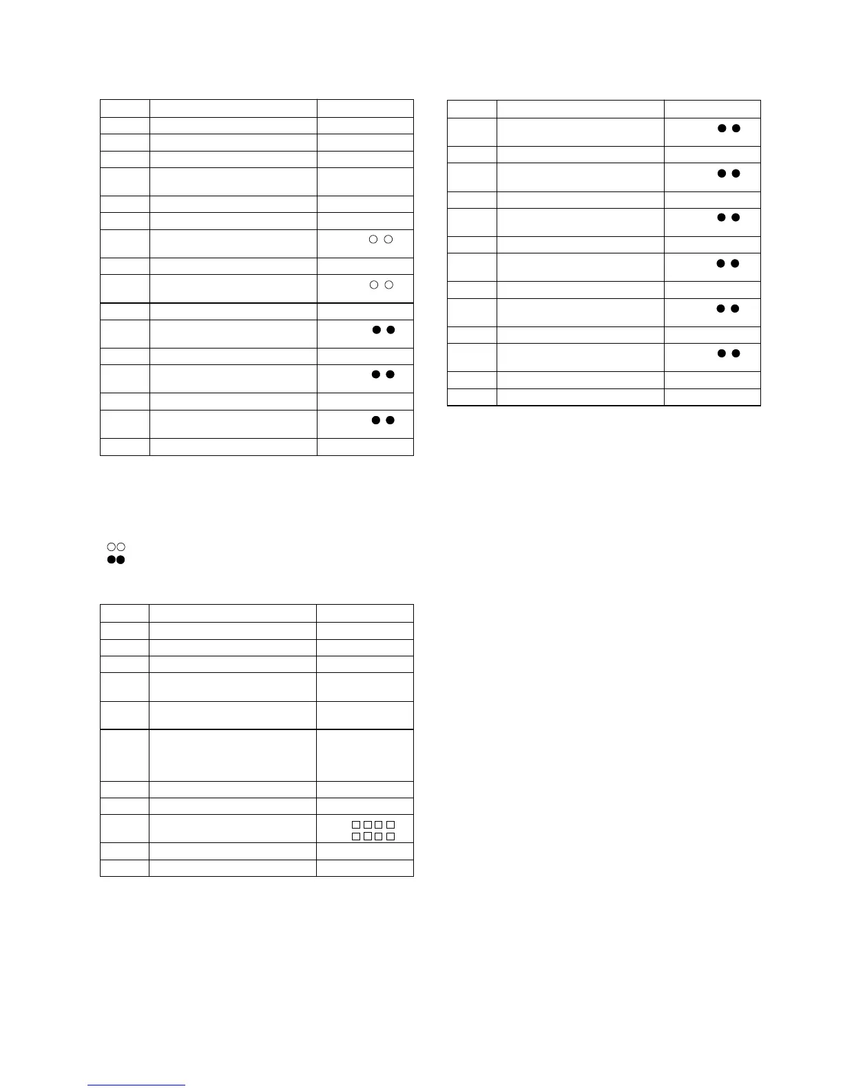
Step No.
Operation and state
Display
3. RESULT Mode
Step 17 Indication of measurement value: [ L f _ _ ]
Low reflection focus gain
Step 18 SKIP UP button
Step 19 Indication of measurement value: [ L g _ _ ]
Low reflection tracking gain
Step 20 SKIP UP button
Step 21 Indication of measurement value: [ L b _ _ ]
Low reflection pit tracking balance
Step 22 SKIP UP button
Step 23 Indication of measurement value: [ G l _ _ ]
Low reflection TOTAL signal level
Step 24 SKIP UP button
Step 25 Indication of measurement value: [ G g _ _ ]
Low reflection groove tracking gain
Step 26 SKIP UP button
Step 27 Indication of measurement value: [ G b _ _ ]
Low reflection groove tracking balance
Step 28 STOP button
Step 29 Test mode STOP state [ T E S T ]
Step No.
Operation and state
Display
• Reversing when the SKIP DOWN button is pressed
• When the VOL UP button is pressed during set value indication, the set value increases, and the new set value is stored in RAM.
• When the VOL DOWN button is pressed during set value indication, the set value decreases, and the new set value is stored in RAM.
• When the VOL UP/DOWN button is held down, the setting changes continuously, one cycle being 100 ms.
• When the STOP button is pressed while the RESULT menu appears, or during measurement value or set value indication, the mode
changes to the TEST mode stop state.
• : Measurement value
• : Set value
7. TEST/PLAY Mode
Step 1 Test mode STOP state [ T E S T ]
Step 2 BASS button
Step 3 AUTO menu [ A U T O ]
Step 4 SKIP UP button x 3times
(Or SKIP DOWN button x 7 times)
Step 5 TEST-PLAY menu [ T _ P L A Y ]
Step 6 When the DISP button is pressed, the
process proceeds to (7).
When the PLAY button is pressed, the
process proceeds to (9).
Step 7 TEST-PLAY mode [ A d 0 0 5 0 ]
Step 8 PLAY button
Step 9 Continuous playback (pit section) [ S Q ]
Continuous playback (groove section) [ A P ]
Step 10 STOP button
Step 11 Test mode STOP state [ T E S T ]
Operation and state
Step No.
Display