MD-MS200W/MD-MS200/MD-MS200H
– 8 –
REMOVING AND REINSTALLING THE MAIN PARTS
Remove the mechanism according to the disassembling meth-
ods 1 to 4. (See Page 7.)
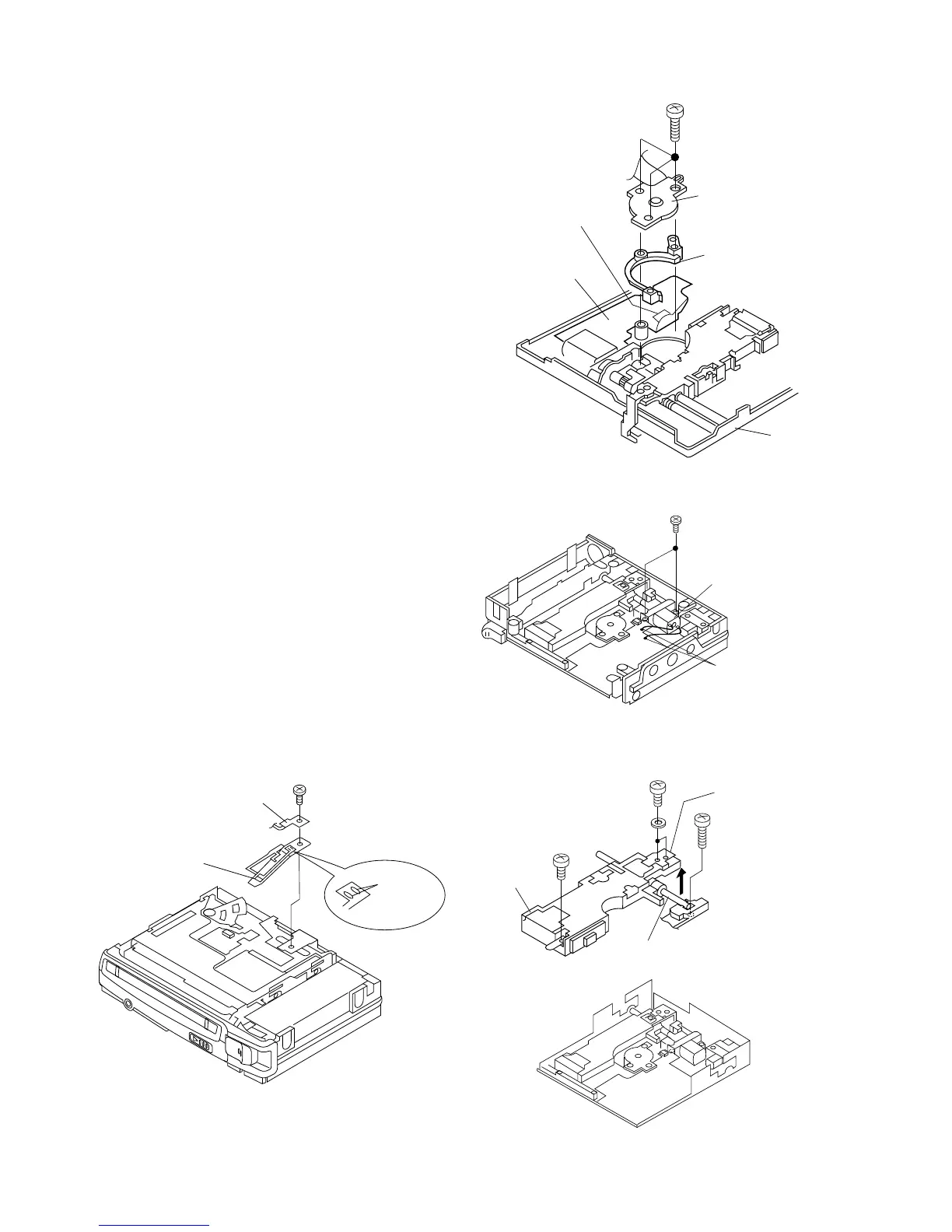
How to remove the disc motor (See Fig. 8-1.)
1. Remove the solder joint (A1) x 1 of flex PWB.
2. Remove the screws (A2) x 3 pcs. and remove the disc
motor.
Take care so that the turnrable is not damaged.
Figure 8-4
(A2) x 3
Ø1.4 x 4.5mm
Flexible PWB
solder joint
(A1) x1
Disc Motor
Motor Spacer
Mechanism PWB
Mechanism
Figure 8-1
(B2) x2
Ø1.4x2.2mm
(B1) x2
Remove the solder joint.
Slide Motor
Figure 8-2
Figure 8-3
Shaft (C2) x 1
(C1) x 2
Ø1.4 x 3mm
(C1) x 1
Ø1.4 x 2.5mm
(C1) x 1
Ø2 x4.5mm
Pickup Unit
Magnetic field arm block
Magnetic head
Head intervening flexible PWB
(D1) x1
Ø1.4x2mm
Unsolder
(D2) x2
How to remove the slide motor (See Fig. 8-2.)
1. Remove the solder joint (B1) x 1 of slide motor lead wire.
2. Remove the screw (B2) x 1, and remove the slide motor.
Note:
Take care so that the motor gear is not damaged.
(If the gear is damaged, noise is raised in search mode.)
How to reinstall the optical pickup unit
(See Fig. 8-3.)
1. Remove the screws (C1) x 5 pcs.
2. Remove the magnetic fielt arm block from the pickup, and
move the magnetic field arm block outwards.
Note:
Take due care so that the magnetic head is not damaged.
3. Withdraw a little the slide motor side shaft (C2) x 1 pcs., and
slowly raise the optical pickup.
How to remove the magnetic head
(See Fig. 8-4.)
1. Remove the screw (D1) x 1 pc.
2. Remove the unsolder (D2) x 2 pcs. which connects the
magnetic head and the head hookup flex.
Note:
Mount carefully so as not to damage the magnetic head.