EasyManua.ls Logo

Sharp MX-1810U - Service Manual

Sharp MX-1810U
191 pages
To Next Page IconTo Next Page
Loading...
SERVICE MANUAL
Parts marked with " " are important for maintaining the safety of the set. Be sure to replace these parts with
specified ones for maintaining the safety and performance of the set.
SHARP CORPORATION
This document has been published to be used
for after sales service only.
The contents are subject to change without notice.
NOTE FOR SERVICING
[1] PRODUCT OUTLINE . . . . . . . . . . . . . . . . . . . . . . . . . . . . . . . . . . . . . . . . . . . . . . . 1-1
[2] CONSUMABLE PARTS . . . . . . . . . . . . . . . . . . . . . . . . . . . . . . . . . . . . . . . . . . . . . 2-1
[3] EXTERNAL VIEW AND INTERNAL STRUCTURE . . . . . . . . . . . . . . . . . . . . . . . . 3-1
[4] ADJUSTMENTS AND SETTINGS . . . . . . . . . . . . . . . . . . . . . . . . . . . . . . . . . . . . . 4-1
[5] SIMULATION . . . . . . . . . . . . . . . . . . . . . . . . . . . . . . . . . . . . . . . . . . . . . . . . . . . . . 5-1
[6] TROUBLESHOOTING . . . . . . . . . . . . . . . . . . . . . . . . . . . . . . . . . . . . . . . . . . . . . . 6-1
[7] FIRMWARE UPDATE . . . . . . . . . . . . . . . . . . . . . . . . . . . . . . . . . . . . . . . . . . . . . . . 7-1
[8] MAINTENANCE . . . . . . . . . . . . . . . . . . . . . . . . . . . . . . . . . . . . . . . . . . . . . . . . . . . 8-1
[9] DISASSEMBLY AND ASSEMBLY . . . . . . . . . . . . . . . . . . . . . . . . . . . . . . . . . . . . . 9-1
[10] VARIOUS STORAGE DATA HANDLING . . . . . . . . . . . . . . . . . . . . . . . . . . . . . . . 10-1
[11] SERVICE WEB PAGE . . . . . . . . . . . . . . . . . . . . . . . . . . . . . . . . . . . . . . . . . . . . . 11-1
[12] OPERATIONAL DESCRIPTIONS. . . . . . . . . . . . . . . . . . . . . . . . . . . . . . . . . . . . . 12-1
[13] ELECTRICAL SECTION. . . . . . . . . . . . . . . . . . . . . . . . . . . . . . . . . . . . . . . . . . . . 13-1
[14] SPECIFICATIONS . . . . . . . . . . . . . . . . . . . . . . . . . . . . . . . . . . . . . . . . . . . . . . . . 14-1
[15] TOOL LIST . . . . . . . . . . . . . . . . . . . . . . . . . . . . . . . . . . . . . . . . . . . . . . . . . . . . . . 15-1
TopPage
CODE: 00ZMX3610/S5E
DIGITAL FULL COLOR
MULTIFUNCTIONAL SYSTEM
MX-1810U/2010U
MX-2310U/3111U
MX-2610N/3110N
MX-3610N
MODEL
CONTENTS

Table of Contents

Other manuals for Sharp MX-1810U

Question and Answer IconNeed help?

Do you have a question about the Sharp MX-1810U and is the answer not in the manual?

Sharp MX-1810U Specifications

General IconGeneral
BrandSharp
ModelMX-1810U
CategoryAll in One Printer
LanguageEnglish

Summary

Note for Servicing

Precautions for Servicing

Provides essential safety guidelines and precautions for servicing the machine.

Warning for Servicing

Lists critical warnings to prevent electrical shock, fire, and injury during service.

Note for Installing Site

Details environmental conditions to avoid for proper machine installation and operation.

Note for Handling PWB and Electronic Parts

Outlines precautions for handling Printed Wiring Boards and electronic parts to prevent static damage.

Screw Tightening Torque

Specifies torque values for screws used in maintenance and repair.

Product Outline

System Diagram

Illustrates the machine's components and their interconnections.

Option List

Lists compatible optional accessories and their installation status.

Consumable Parts

Supply System Table

Details consumable parts, their model names, and quantities per package.

Maintenance Parts List

Lists parts required for routine maintenance procedures.

Definition of Developer;Drum Life End

Explains the criteria used to determine when developer or drum components reach their end of life.

External View and Internal Structure

External View

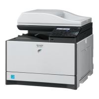
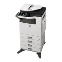
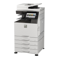
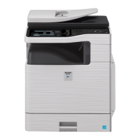
Shows the exterior of the machine, identifying key external features and components.

Internal Structure

Illustrates the internal layout, identifying major internal parts and their functions.

Operation Panel

Details the functions and layout of the machine's control panel.

Sensors and Detectors

Lists and describes the function of various sensors and detectors within the machine.

Switches

Identifies and describes the purpose of various switches used in the machine.

PWB;Memory Device

Identifies and describes the function of the machine's Printed Wiring Boards and memory components.

Adjustments and Settings

General

Provides overarching instructions and precautions for performing adjustments.

Adjustment Item List

A comprehensive list of all adjustable items with their corresponding Job numbers.

Details of Adjustment

Provides step-by-step instructions for performing specific machine adjustments.

Simulation

General and Purpose

Explains the functions and benefits of using the simulation mode.

Starting the Simulation

Guides users on how to access and start the simulation mode.

List of Simulation Codes

A reference table mapping simulation codes to their specific functions.

Details of Simulation

Provides detailed procedures for executing various simulation tests.

Related product manuals