10
E
Part Names
n
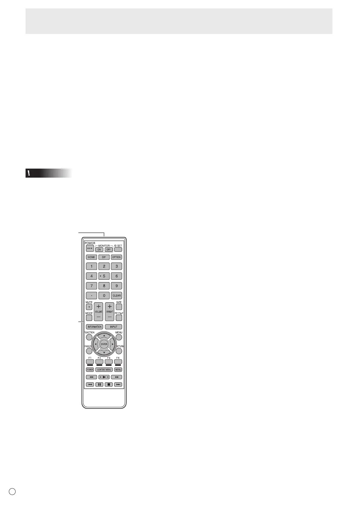
Remote control unit
2
1. Signal transmitter
2. Operation buttons (See pages 17 and 19.)
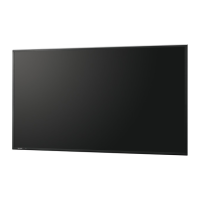
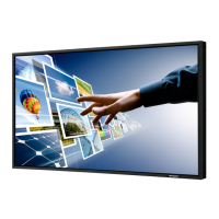
1. LCD panel
2. Power button (See page 17.)
3. Input button (See page 20.)
4. Power LED (See page 17.) / Remote control sensor
(See page 15.)
5. AC input terminal (See page 13.)
6. Main power switch (See page 13.)
7. DisplayPort output terminal (See page 11.)
8. HDMI1 input terminal (See page 12.)
9. HDMI2 input terminal (See page 12.)
10. DisplayPort input terminal (See page 12.)
11. DVI-D input terminal (See page 12.)
12. D-sub input terminal (See page 12.)
13. Vents
14. Speakers
15. Expansion slot
This section is used to connect optional hardware for
function expansion. Offering this attachment location
is not a guarantee that future compatible hardware
attachments will be released.
16. 5 V power supply terminal (See page 12.)
17. LAN terminal (See page 12.)
18. RS-232C output terminal (See page 12.)
19. RS-232C input terminal (See page 12.)
20. Optional terminal
This terminal is provided for possible future (optional)
function expansion. Offering of this terminal is not a
guarantee that future expanded functionality will be
released.
21. Audio output terminal (See page 12.)
22. Audio input terminal (See page 12.)
23. Handle (PN-R706/PN-R606 only; two handles on the
PN-R606)
Caution
• Consult your SHARP dealer for attachment/detachment of optional parts.