12
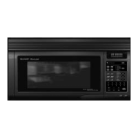
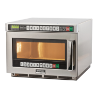
R-1610
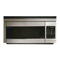
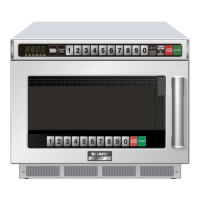
R-1611
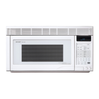
R-1612
DESCRIPTION OF LSI
LSI(IZA958DR)
The I/O signal of the LSI(IZA958DR) is detailed in the following table.
Pin No. Signal I/O Description
NOTE: For additional informations of LSI, please refer back to the R-1600/1601/
1602 base model Service Manual.
1 AN10 IN Signal coming from touch key.
When either G10 line on key matrix is touched, a corresponding signal out of P10-P17 will
be input into AN10. When no key is touched, the signal is held at "H" level.
9 P15 OUT
Key strobe signal.
Signal applied to touch-key section. A pulse signal is input to AN9, AN10, AN11, P41 and
P42 terminal while one of G3 line keys on key matrix is touched.
10 P16 OUT
Key strobe signal.
Signal applied to touch-key section. A pulse signal is input to AN8, AN9, AN10, AN11, P41
and P42 terminal while one of G2 line keys on key matrix is touched.
11 P17 OUT
Key strobe signal.
Signal applied to touch-key section. A pulse signal is input to AN9, AN10, AN11, P41 and
P42 terminal while one of G1 line keys on key matrix is touched.
29 P32 OUT Terminal not used.
30-34 P33-P37 OUT Used for initial balancing of the bridge circuit (absokute humidity sensor).
91 AN0 IN Used for initial balancing of the bridge circuit (absokute humidity sensor). This input is an
analog input terminal from the AH sensor circuit, and connected to the A/D converter built
into the LSI.
92 AN1 IN
AH sensor input.
This input is an analog input terminal from the AH sensor circuit, and connected to the A/
D converter built into the LSI.
99 AN8 IN
Input terminal to judge the model.
The signal out of P16 will be input into AN8 through G2 line on key matrix. The LSI will judge
the model by this signal.