18
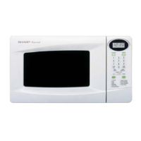
R-22AM
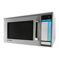
R-23AM
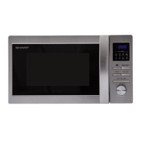
R-23AT
CARRY OUT 3D CHECKS.
Remove the outer case and check voltage between Pin Nos. 5 and 7 of the connector (A) on the control
unit with an A.C. voltmeter. The meter should indicate 230 volts, if not check control unit circuity.
RY1, RY3 and RY4 Relay Test For R-23AT
These relays are operated by D.C. voltage.
Check voltage at the relay coil with a D.C. voltmeter during the microwave cooking operation.
DC. voltage indicated .............................Defective relay.
DC. voltage not indicated .......................Check diode which is connected to the relay coil. If
diode is good, control unit is defective.
RELAY SYMBOL OPERATIONAL VOLTAGE CONNECTED COMPONENTS
RY1 APPROX. 19.0V D.C. Oven lamp, Blower motor and Stirrer motors
RY3 APPROX. 16.0V D.C. High voltage transformer 1
RY4 APPROX. 18.0V D.C. High voltage transformer 2
RY1, RY2 and RY3 Relay Test For R-23AM / R-22AM
These relays are operated by D.C. voltage.
Check voltage at the relay coil with a D.C. voltmeter during the microwave cooking operation.
DC. voltage indicated .............................Defective relay.
DC. voltage not indicated .......................Check diode which is connected to the relay coil. If
diode is good, control unit is defective.
TEST PROCEDURES
PROCEDURE
LETTER COMPONENT TEST
Q RELAY TEST
CARRY OUT 4R CHECKS.
SWITCH UNIT TEST FOR R-23AM / R-22AM
1. CARRY OUT 3D CHECKS.
2. Remove the switch unit from the control panel, referring to control panel removal.
3. To test the switches (SW1-SW5) on the switch unit, check between the terminals of the connector
CN-F as described in the following table by using ohmmeter when the switches are released and
depressed.
Switches Terminals Released Depressed
SW1 F1 - F4 O.C. S.C.
SW2 F1 - F5 O.C. S.C.
SW3 F2 - F4 O.C. S.C.
SW4 F2 - F5 O.C. S.C.
SW5 F3 - F4 O.C. S.C.
4. If incorrect readings are obtained, replace the defective switch.
5. CARRY OUT 4R CHECKS.
G 9
G 10
G 11
G 12
G 8
1
11
12
13
14
15
16
19
20
17
18
2
3
4
5
6
7
8
9
0
G 7 G 6 G 5 G 4 G 3 G 2 G 1
X2