R-22GT-F
R-22GV-F
21
Pin No. Signal I/O Description
DESCRIPTION OF LSI
LSI(IZA633DR)
The I/O signal of the LSI(IZA633DR) is detailed in the following table.
1 VCC IN Power source voltage: +5V.
VC voltage of power source circuit input.
2/3 VEE/AVSS IN Connected to GND
4 VREF IN Connected to VC. (+5V)
5 AN7 IN
Temperature measurement input: INTAKE THERMISTOR.
By inputting DC voltage corresponding to the temperature detected by the thermistor, this input
is converted into temperature by the A/D converter built into the LSI.
6 AN6 IN Connected to GND.
7-8 AN5-AN4 IN
Terminal to change functions according to the model.
Signal in accordance with the model in operation is applied to set up its function.
9 AN3 IN A/D input for troubleshooting Magnetron 1. and/or Magnetron 2.
10 AN2 IN
Temperature measurement input: OVEN THERMISTOR.
By inputting DC voltage corresponding to the temperature detected by the thermistor, this input
is converted into temperature by the A/D converter built into the LSI.
11 AN1 IN Input signal which communicates the door open/close information to LSI.
Door closed; "L" level signal (0V).
Door opened; "H" level signal (+5V).
12 AN0 IN
Temperature measurement input: FAN LOCK THERMISTOR.
By inputting DC voltage corresponding to the temperature detected by the thermistor, this input
is converted into temperature by the A/D converter built into the LSI.
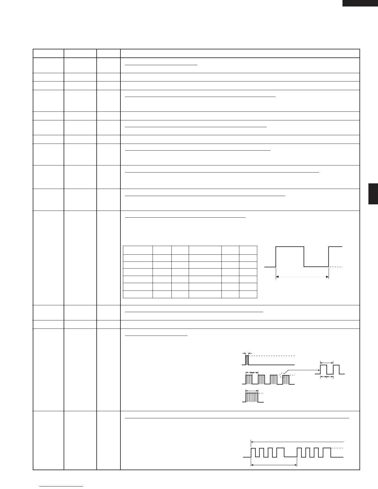
13-14 P55-P54 OUT
Magnetron high-voltage circuit driving signal.
To turn on and off the cook relay. In 100% power level operation, "H" level during cooking; "L" level
otherwise. In other power level operation (90,80,70,60,50,40,30,20,10 or 0%), "H" and "L" level
is repeated according to power level.
Power level ON OFF Power level ON OFF
100% 32sec. 0sec. 40% 16sec. 16sec.
90% 30sec. 2sec. 30% 12sec. 20sec.
80% 26sec. 6sec. 20% 8sec. 24sec.
70% 24sec. 8sec. 10% 6sec. 26sec.
60% 22sec. 10sec. 0% 0sec. 32sec.
50% 18sec. 14sec.
15 P53 OUT Oven thermistor circuit power supply control signal.
Output the "H" signal to supply power to oven thermistor circuit about 1.7msec. after plugging in.
16-18 P52-P50 IN Terminal not used.
19 P47 OUT
Signal to sound buzzer.
This signal is to control the 2.5kHz continuous signal through IC3.
A: key touch sound.
B: Guydance sound.
C: Completion sound.
20 P46 OUT Oven lamp, Blower motor and Stirrer motor driving signal. (Square Waveform : 60Hz)
To turn on and off the shut-off relay (RY1). The Square waveform voltage is delivered to the RY1
driving circuit and relays(RY2,RY3,COOK RELAY) control circuit.
+5V
GND
32 sec.
ON
OFF
A
0.1 sec
2 sec
1 sec
+5V
GND
T
200µsec.
200µsec.
1 sec
B
+5V
GND
C
+5V
GND
L
16.7 msec
During cooking
 Loading...