6
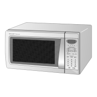
R-310AK
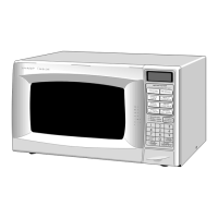
R-330AK
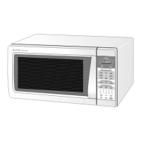
R-330AW
Pin No. Signal I/O Description
LSI(IZA758DR) : R-310AK
The I/O signal of the LSI(IZA758DR) is detailed in the following table.
Pin No. Signal I/O Description
67 SEG23 OUT Terminal not used.
68-74
SEG22-SEG16 OUT Segment data signal.
Signal similar to SEG27.
75 SEG15 OUT Terminal not used.
76-82
SEG14-SEG8 OUT Segment data signal.
Signal similar to SEG27.
83 SEG7 OUT Terminal not used.
84-90
SEG6-SEG0 OUT Segment data signal.
Signal similar to SEG27.
91/92
VCC/VREF IN Connected to GND.
93 AVSS IN Connected to VC.
94 COM3 OUT
Common data signal: COM3.
Connected to LCD (Pin No. C0).
95 COM2 OUT
Common data signal: COM2.
Connected to LCD (Pin No. C1).
96 COM1 OUT
Common data signal: COM1.
Connected to LCD (Pin No. C2).
97 COM0 OUT
Common data signal: COM0.
Connected to LCD (Pin No. C3).
98-99 VL3-VL2 IN
Power source voltage input terminal.
Standard voltage for LCD.
100 C2 IN Terminal not used.
1-12
SEG0-SEG11 OUT Segment data signal.
Connected to LCD.
The relation between signals are as follows:
LSI signal (Pin No.) LCD (Pin No.) LSI signal (Pin No.) LCD (Pin No.)
SEG 0 (1) ................................... S12 SEG 6 (7) ....................................S6
SEG 1 (2) ................................... S11 SEG 7 (8) ....................................S5
SEG 2 (3) ................................... S10 SEG 8 (9) ....................................S4
SEG 3 (4) .....................................S9 SEG 9 (10) ..................................S3
SEG 4 (5) .....................................S8 SEG 10 (11) ................................S2
SEG 5 (6) .....................................S7 SEG 11(12) .................................S1
13 R60 IN
Signal coming from touch key.
When either G12 line on key matrix is touched, a corresponding signal out of R73, R81-R83
and R90-R91 will be input into R60. When no key is touched, the signal is held at "H" level.
14 R61 IN
Signal similar to R60.
When either G11 line on key matrix is touched, a corresponding signal will be input into R61.
15 R62 IN
Signal similar to R60.
When either G10 line on key matrix is touched, a corresponding signal will be input into R62.
16 R63 IN
Signal similar to R60.
When either G9 line on key matrix is touched, a corresponding signal will be input into R63.
17 AIN0 IN
To input signal which communicates the door open/close information to LSI.
Door close "H" level signal (0V). Door open "L" level (-5V)
18-20
AIN1-AIN3 IN Terminal to change functions according to the Model.
By using the A/D converter contained in the LSI, DC voltage in accordance with the Model
in operation is applied to set up its function.
21 VSS IN
Power source voltage: -5V
VSS voltage of power source circuit input.