Do you have a question about the Sharp R-350Y and is the answer not in the manual?
Provides essential operational and service information for Sharp Corp. Service engineers.
Guidelines to prevent exposure to microwave energy during servicing of the oven.
Critical safety points to ensure before operating or servicing the microwave oven.
Essential checks and procedures to perform before commencing service on the microwave oven.
Steps to follow after completing testing, including reassembly and final checks.
Steps for verifying repair work, including microwave output and leakage tests.
Procedures to re-check connections before replacing a Printed Wiring Board due to potential harness issues.
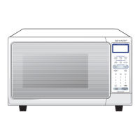
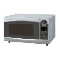
Visual identification of external and internal oven components and their locations.
Diagram and explanation of the touch control panel layout and its various pads.
Describes the sequence of events and switch states when the oven is in the off mode.
Details the operational steps and component states during microwave cooking.
Explains the sequence of operations and sensor function during sensor cooking.
Information on how microwave power levels are reduced over time to prevent overheating.
Explains the mechanical operation of the oven door opening mechanism.
Describes the function and contact states of the door interlock switches.
Details the role and contact operation of the monitor switch in the door mechanism.
Explains the purpose of Fuse F10A and conditions under which it blows.
Describes the function of the inverter unit in converting voltage for the magnetron.
Explains the function of the oven temperature fuse for safety against overheating.
Details the function of the motor that rotates the turntable.
Explains the fan motor's role in cooling the magnetron and circulating air.
Describes the noise filter's role in preventing radio frequency interference.
Explains how the humidity sensor detects moisture for automatic cooking control.
Detailed steps for testing the magnetron, including filament continuity and short circuit tests.
Instructions for testing various switches using an ohmmeter for continuity and open/closed states.
Steps for testing the temperature fuse, checking for continuity in its 'ON' condition.
Procedure for testing fan and turntable motor windings by measuring resistance.
Guidance on troubleshooting blown Fuse F10A, including checks for shorts and door switches.
Steps for testing the noise filter using an ohmmeter to check for short circuits.
Methods for testing the touch control panel assembly, including Key Unit and Control Unit diagnostics.
Procedure for testing the key unit and identifying faults in the membrane switch.
Troubleshooting steps when Fuse F1 on the printed wiring board is open.
Detailed procedures for testing the humidity sensor and control unit, including water load tests.
Comprehensive guide to servicing the touch control panel, including precautions and tools.
Essential precautions for handling CMOS LSI components to prevent damage from static electricity.
Procedures for servicing the touch control panel using the oven's power or an external source.
Lists the necessary tools and equipment required for servicing the touch control panel.
Further precautions to take during touch control panel servicing, focusing on static electricity and connections.
Information on identifying and using lead-free solder on the main PWB.
Guidelines for using lead-free wire solder to avoid cold joints and damage to PCBs.
Precautions and techniques for soldering with lead-free solder to prevent PWB damage and ensure good joints.
Critical safety checks and warnings to perform before operating the oven after servicing.
Step-by-step instructions for removing and reinstalling the inverter unit.
Detailed procedures for safely removing and replacing the magnetron component.
Instructions for disconnecting positive lock connectors, with specific attention to lever orientation.
Steps for removing the control panel assembly from the oven.
Procedure for replacing the graphic sheet and membrane switch on the control panel.
Detailed steps for removing and reinstalling the turntable motor.
Instructions for removing and reinstalling the cooling fan motor and its blade.
Procedure for safely replacing the power supply cord.
Steps for removing the latch switches and monitor switch.
Procedure for adjusting the door latch hook to ensure proper switch operation.
Comprehensive steps for removing and replacing the microwave oven door.
Schematic diagrams illustrating the oven's electrical circuits in OFF and ON conditions.
Visual representation of component connections and wiring harness layout.
Detailed circuit diagram for the oven's control unit.
Diagram showing the layout of components and connections on the power unit's PWB.
Circuit diagram illustrating the internal workings of the inverter unit.
| Brand | Sharp |
|---|---|
| Model | R-350Y |
| Category | Microwave Oven |
| Language | English |