23
R-330BK
R-330BW
Pin No. Signal I/O Description
16.7 msec.
During cooking
H : GND
L : -5V
P-HI
H : GND
L : -5V
H : GND
L : -5V
P-70
ON
ON
OFF
OFF OFF
24 sec.
8 sec.
16.7 msec.
H : GND
L : -5V
79 VCC IN Power source voltage: GND (0V).
The power source voltage to drive the LSI is input to VCC terminal.
80-84 P10-P14 OUT Used for initial balancing of the bridge circuit (absolute humidity sensor).
85-86 P15-P16 OUT Terminal not used.
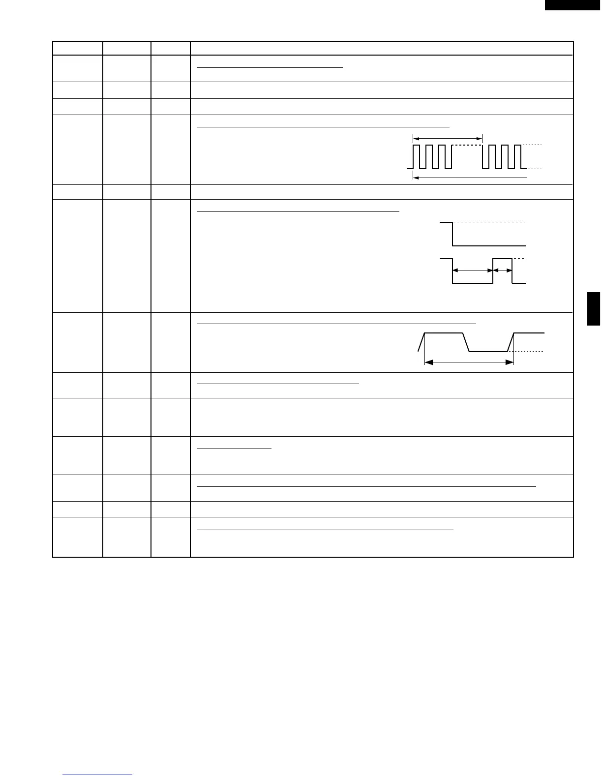
87 P17 OUT
Oven lamp, fan motor and turntable motor driving signal.
To turn on and off shut off relay (RY1). The
square waveform voltage is delivered to the
RY1 driving circuit and RY2 control circuit.
88-89 P40-P41 OUT Terminal not used.
90 P42 OUT
Magnetron high-voltage circuit driving signal.
To turn on and off the cook relay (RY2). The
signals holds "L" level during microwave cook-
ing and "H" level while not cooking. In other
cooking modes (variable cooking) the signal
turns to "H" level and "L" level in repetition
according to the power level.
(ON and OFF times for other power level.)
91 IRQ0 IN
Signal synchronized with commercial power source frequency.
This is the basic timing for time processing of LSI.
92 AVCC IN
A/D converter power source voltage.
The power source voltage to drive the A/D converter in the LSI. Connected to GND.
93 AN0 IN Used for initial balancing of the bridge circuit (absolute humidity sensor). This input is an
analog input terminal from AH sensor circuit, and connected to the A/D converter built into the
LSI.
94 AN1 IN
AH sensor input.
This input is an analog input terminal from the AH sensor circuit, and connected to the A/D
converter built into the LSI.,
95 AN2 IN
To input signal which communicates the door open/close information to LSI.
Door close "H" level signal (0V). Door open "L" level signal (-5V)
96 AN3 OUT Terminal not used.
97-100 AN4-AN7 IN
Terminal to change cooking input according to the Model.
By using the A/D converter contained in the LSI, DC voltage in accordance with the Model in
operation is applied to set up its cooking constant.