23
R-430DK
R-430DW
R-430DQ
R-440DK
R-440DW
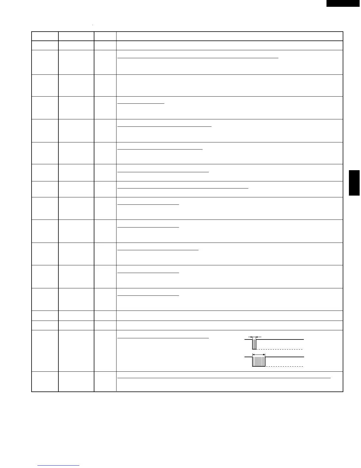
27 AVSS IN Connected to VC.
28-31 ANI0-ANI3 IN Terminal to change cooking input according to the Model.
By using the A/D converter contained in the LSI, DC voltage in accordance with the
Model in operation is applied to set up its cooking constant.
32 ANI4 IN Used for initial balancing of the bridge circuit (absolute humidity sensor). This input is
an analog input terminal from the AH sensor circuit, and connected to the A/D
converter built into the LSI.
33 ANI5 IN AH sensor input.
This input is an analog input terminal from the AH sensor circuit, and connected to
the A/D converter built into the LSI.
34 ANI6 IN Input terminal to judge the model.
The signal out of P114 will be input into ANI6 through G4 line on key matrix. The LSI
will judge the model by this signal.
35 ANI7 IN Signal coming from touch key.
When either G13 line on key matrix is touched, a corresponding signal out of P110 -
P117 will be input into ANI7. When no key is touched, the signal is held at "H" level.
36 VDD0 IN Power source voltage : GND(0V).
The power source voltage to drive LSI is input to VDD0 terminal.
37 AVREF IN A/D converter power source voltage : GND(0V).
The power source voltage to drive the A/D converter. Connected to GND.
38 P100 IN Signal similar to ANI7.
When either G12 line on key matrix is touched, a corresponding signal will be input
into P100.
39 P101 IN Signal similar to ANI7.
When either G11 line on key matrix is touched, a corresponding signal will be input
into P101.
40 VSS1 IN Power source voltage : -5.0V.
The power source voltage to the drive LSI is input to VSS1 terminal. Connected to
VC.
41 P102 IN Signal similar to ANI7.
When either G10 line on key matrix is touched, a corresponding signal will be input
into P102.
42 P103 IN Signal similar to ANI7.
When either G9 line on key matrix is touched, a corresponding signal will be input into
P103.
43 P30 OUT Terminal not used.
44-48 P31-P35 OUT Used for initial balancing of the bridge circuit (absolute humidity sensor).
49 P36 OUT Signal to sound buzzer (2.0 kHz).
A: key touch sound.
B: Completion sound.
50 P37 IN To input signal which communicates the door open/close information to LSI.
Door close "H" level signal (0V). Door open "L" level signal (-5V).
Pin No. Signal I/O Description
A
B
0.1 sec.
2.0 sec.
H : GND
L : -5V
H : GND
L : -5V