28
R-430DK
R-430DW
R-430DQ
R-440DK
R-440DW
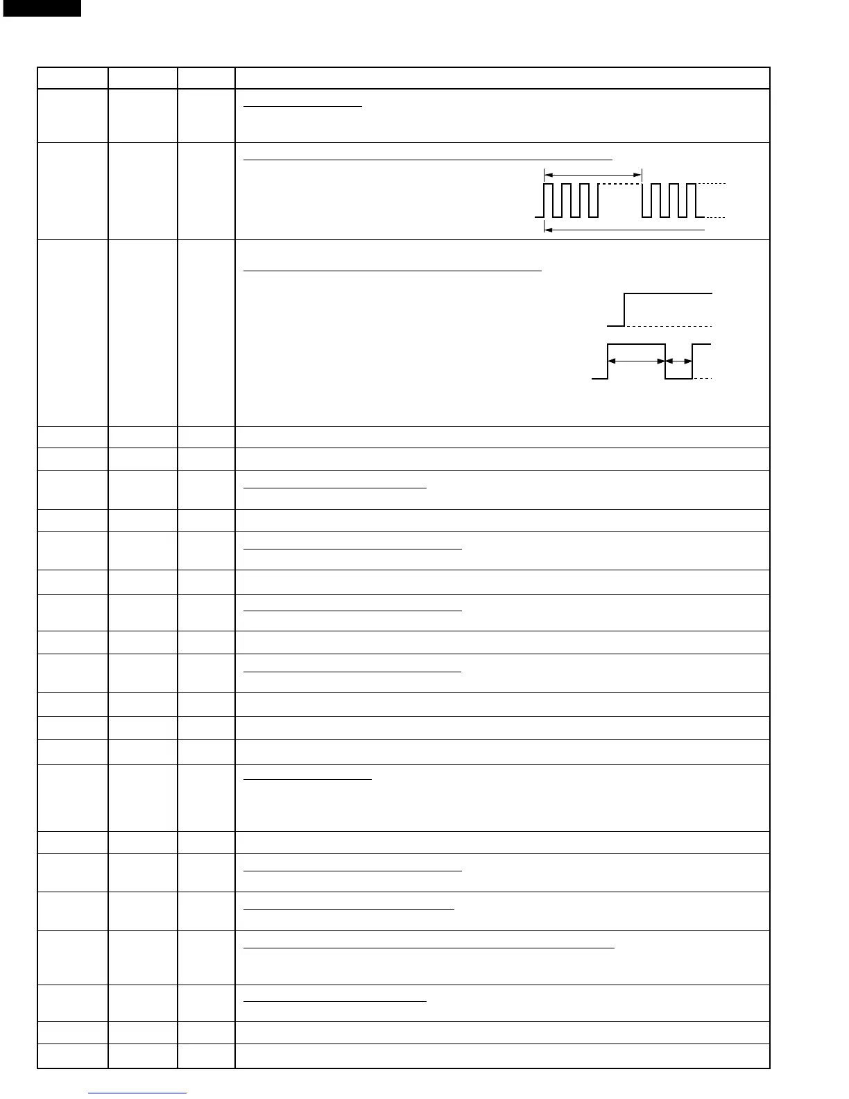
25 P44 OUT Key strobe signal.
Signal applied to touch screen section. A pulse signal is input to PB1-PB5 terminal
while one of G10 line keys on key matrix is touched.
26 P45 OUT Oven lamp, fan motor and turntable motor driving signal
To turn on and off shut off relay (RY1). The
square waveform voltage is delivered to
the RY1 driving circuit and RY2 control
circuit.
27 P46 OUT Magnetron high-voltage circuit driving signal.
To turn on and off the cook relay (RY2).
The signals holds "H" level during
microwave cooking and "L" level while not
cooking. In other cooking modes (variable
cooking) the signal turns to "L" level and
"H" level in repetition according to the power
level.
(ON and OFF times for other power level.)
28 P47 OUT Terminal not used.
29-36 D8-D15 OUT Data signal is output to IC2 and IC5.
37 Vcc IN Power source voltage : +5V.
The power source voltage to drive LSI is input to Vcc terminal. Connected to VCC.
38-45 A0-A7 OUT Address signal is output to IC2 and IC5.
46 Vss IN Power source voltage : GND (0V).
The power source voltage to drive LSI is input to Vss terminal.
47-58 A8-A19 OUT Address signal is output to IC2 and IC5.
59 Vss IN Power source voltage : GND (0V).
The power source voltage to drive LSI is input to Vss terminal.
60 WATT IN Connected to VCC.
61 P61 OUT Envelope signal to sound buzzer.
A: key touch sound (short beep). B: Completion sound (melody or long beep).
62 P62 OUT Reset signal is output to IC5.
63 P67 OUT Terminal not used.
64 STBY IN Connected to VCC.
65 RES IN Auto clear terminal.
Signal is input to reset the LSI to the initial state when power is applied. Temporarily
set "L" level the moment power is applied, at this time the LSI is reset. Thereafter set
at "H" level.
66 NMI IN Connected to GND.
67 Vss IN Power source voltage : GND (0V).
The power source voltage to drive LSI is input to Vss terminal.
68 EXTAL OUT Internal clock oscillation output.
Output to control oscillation input to EXTAL.
69 XTAL IN Internal clock oscillation frequency control input setting.
The internal clock frequency is set by inserting the ceramic filter oscillation circuit
with respect to XTAL.
70 Vcc IN Power source voltage : +5V.
The power source voltage to drive LSI is input to Vcc terminal. Connected to VCC.
71 AS OUT Terminal not used.
72 RD OUT Read strobe signal is output to RD terminal of IC5.
Pin No. Signal I/O Description
16.7 msec.
During cooking
H : +5V
L : GND
100
PERCENT
70
PERCENT
H : +5V
L : GND
H : +5V
L : GND
ON
ON
OFF
OFF
24 sec.
8 sec.