R -4A52
R-4E52
PIN NO.
j 22-24 SIGNAL / Dll-D9
I
I/O
/ OUT
Diqit selection siqnal.
Refer to the touch control panel circuit about the relation between signals and digits.
Normally, one pulse is output in every synchronized signal period, and input to the grid of the fluorescent display.
PIN NO. j 25-27
.I SIGNAL i D8-D6
I I/O
1 OUT
Diqit selection siqnal.
Signal similar to Dl I.
PIN NO. / 28
Seqment data siqial.
Signal similar to FO.
1 SIGNAL / D5
I
I/O
/ OUT
PIN NO. 1 29-31
1 SIGNAL 1 D4-D2
I
I/O
/ OUT
Terminal not used.
PIN NO. 1 32
1 SIGNAL j Dl
Maqnetron Hiqh-voltaqe circuit drivinq siqnal.
To turn on and off the cook relay.
I
I/O
1 OUT
In high operation, the signals holds “H” level during microwave cooking and “L” level while not cooking. In other
cooking modes (MED. HIGH, MED., MED. LOW, LOW) the signal turns to “H” level and “L” level in repetition
according to the power level.
PIN NO. / 33
I
1 SIGNAL 1 DO
I
I/O
1 OUT
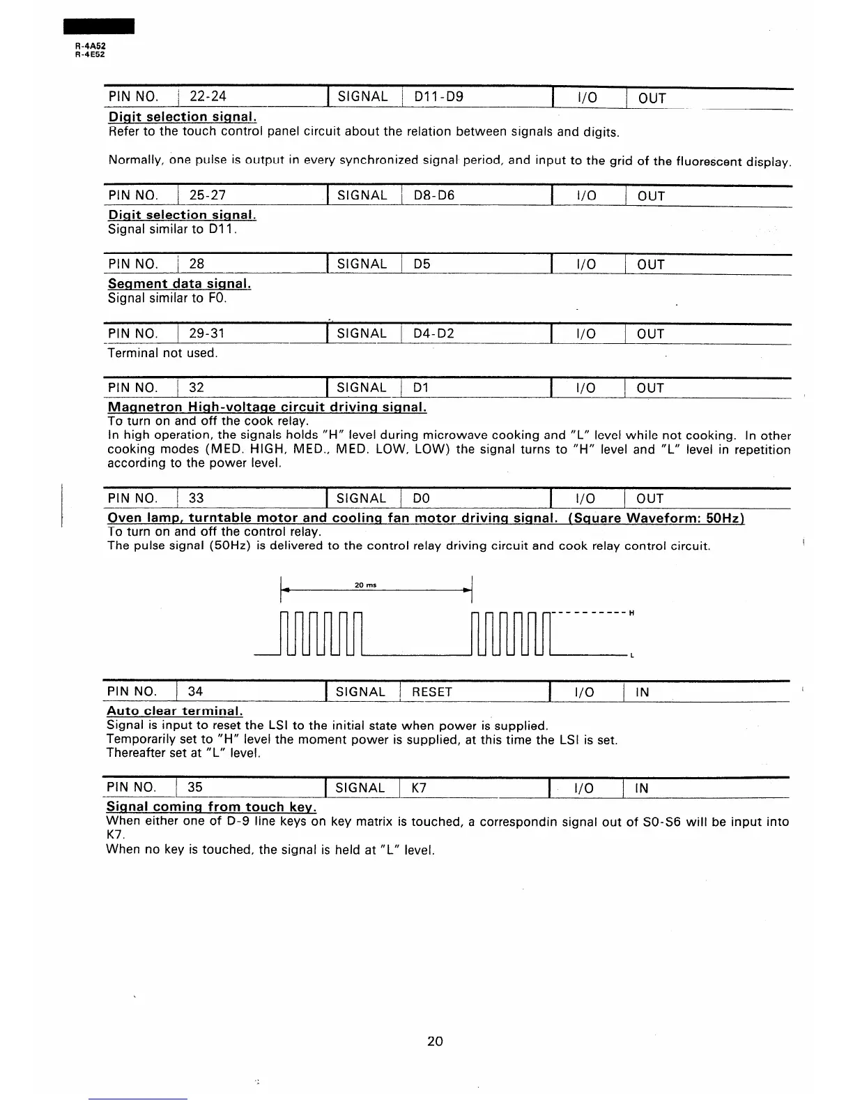
&en lamp, turntable motor and coolinq fan motor drivinq siqnal. (Square Waveform: 50Hzl
To turn on and off the control relay.
The pulse signal (50Hz) is delivered to the control relay driving circuit and cook relay control circuit.
I
c--7
v----c
----------H
L-LA--
d-.-d-
L
PIN NO. j 34
Auto clear terminal.
1 SIGNAL ) RESET
I
I/O
/ IN
I
Signal is input to reset the LSI to the initial state when power is supplied.
Temporarily set to “H” level the moment power is supplied, at this time the LSI is set.
Thereafter set at “L” level.
PIN NO. 35
I
1 SIGNAL 1 K7
I
l/O
1 IN
Sinnal coming from touch key.
When either one of D-9 line keys on key matrix is touched, a correspondin signal out of SO-S6 will be input into
K7.
When no key is touched, the signal is held at “L” level,
20