R-4A52
R-4E52
\
Tab of the door panel
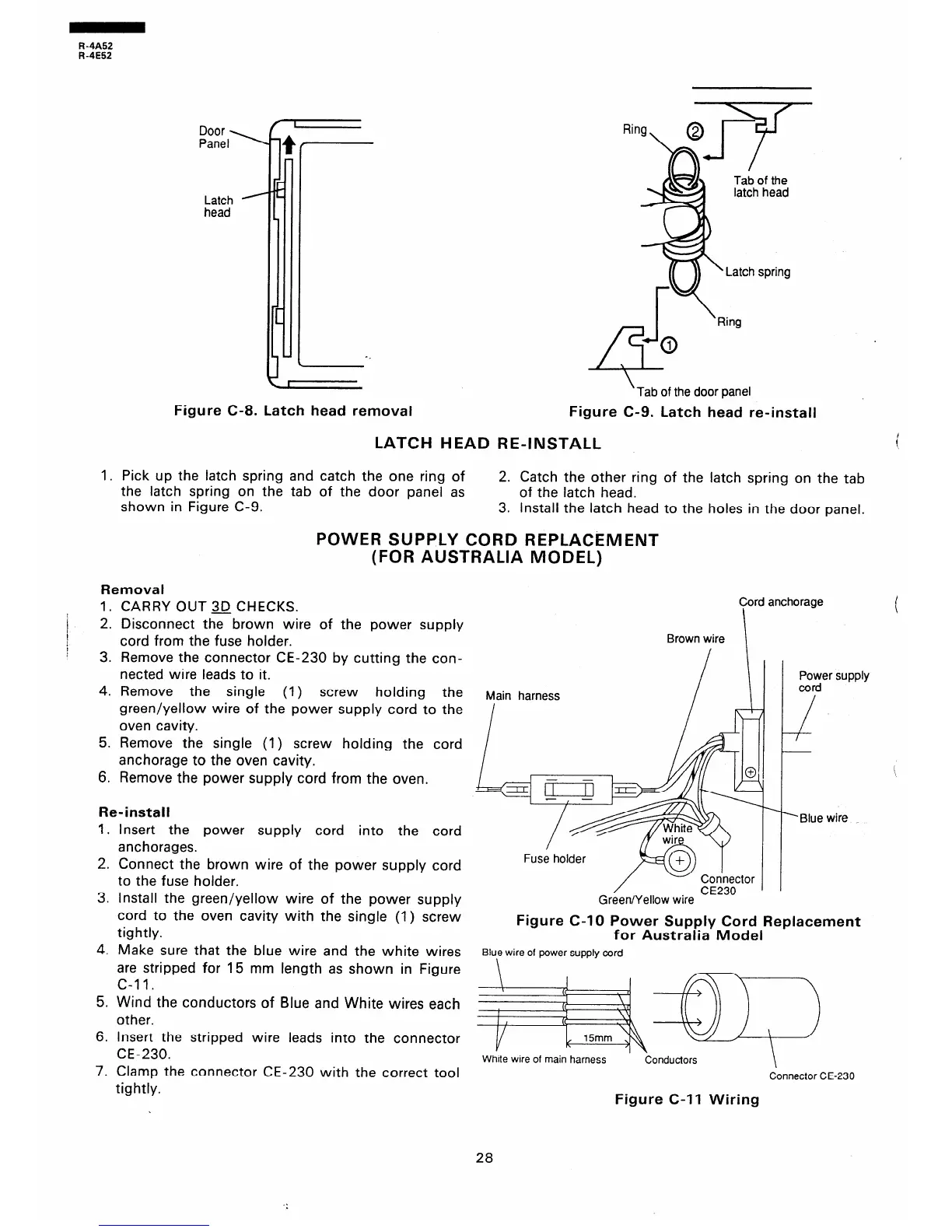
Figure C-8. Latch head removal
Figure C-9. Latch head re-install
LATCH HEAD RE-INSTALL
1. Pick up the latch spring and catch the one ring of
the latch spring on the tab of the door panel as
shown in Figure C-9.
2. Catch the other ring of the latch spring on the tab
of the latch head.
3. Install the latch head to the holes in the door panel.
POWER SUPPLY CORD REPLACEMENT
(FOR AUSTRALIA MODEL)
Removal
1. CARRY OUT 30 CHECKS.
2. Disconnect the brown wire of the power supply
cord from the fuse holder.
3. Remove the connector CE-230 by cutting the con-
nected wire leads to it.
4. Remove the single (1) screw holding the
green/yellow wire of the power supply cord to the
oven cavity.
5. Remove the single (1) screw holding the cord
anchorage to the oven cavity.
6. Remove the power supply cord from the oven.
Re-install
1. Insert the power supply cord into the cord
anchorages.
2. Connect the brown wire of the power supply cord
to the fuse holder.
3. Install the green/yellow wire of the power supply
cord to the oven cavity with the single (1) screw
tightly.
4. Make sure that the blue wire and the white wires
are stripped for 15 mm length as shown in Figure
C-II.
5. Wind the conductors of Blue and White wires each
other.
6. Insert the stripped wire leads into the connector
CE-230.
7. Clamp the connector CE-230 with the correct tool
tightly.
Cord anchorage
I
Brown wire \
Fuse holder
Green/Yellow wire
Figure C-10 Power Supply Cord Replacement
for Australia Model
Blue wire of power supply cord
White wire of main harness
33::
Conductors
Connector CE-230
Figure C-II Wiring
28