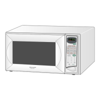
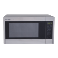
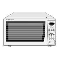
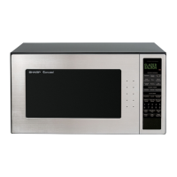
This document is a service manual for the Sharp R-520KS microwave oven, providing comprehensive information for service personnel.
Function Description
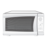
The Sharp R-520KS is a microwave oven designed for cooking, reheating, and defrosting food. It utilizes microwave energy to heat food, with a magnetron generating the microwaves which are then channeled into the oven cavity. The oven features a touch control panel for programming various cooking functions, including variable power levels and sensor cooking.
Operating Sequence:
When the oven is plugged in and the door is closed, the control unit receives 120V AC. The display shows "88:88" until the STOP/CLEAR pad is touched, clearing the display to " : ".
Upon touching the START pad after programming, relays (RY-1 and RY-2) close, activating the oven lamp, turntable motor, fan motor, and power transformer. The power transformer converts 120V AC to approximately 3.3V AC for the magnetron filament and 2370V AC for the high voltage winding, which is then sent to a voltage doubler circuit. The heated magnetron produces microwave energy, channeled into the cavity for cooking.
After cooking, components turn off, and microwave generation stops. If the door is opened during a cook cycle, the monitor switch, door sensing switch, primary interlock switch, and secondary interlock relay activate, de-energizing high voltage components, turntable, and cooling fan, while the oven lamp remains on and the display shows remaining time. The monitor switch also electrically monitors the interlock switches and relay, blowing a fuse if they fail to open when the door is opened.
Variable Cooking Power (P-0 to P-90):
The oven supplies 120V AC to the power transformer intermittently via relay RY-2, controlled by the unit within a 32-second time base. Power operation varies from 100% (P-HI, 32 sec ON) to 0% (P-0, 0 sec ON, 32 sec OFF), with intermediate levels like P-90 (90% power, 30 sec ON, 2 sec OFF) and P-50 (50% power, 18 sec ON, 14 sec OFF). The ON/OFF time ratio does not directly correspond to the percentage of microwave power due to the 2 seconds required for magnetron filament heating.
Sensor Cooking:
This feature allows cooking without manual time, power, or quantity settings. The oven senses steam from food, relays information to the microprocessor, which then calculates remaining cooking time and power level. As food cooks, water vapor increases, and the sensor's resistance rises. Once the resistance reaches a preset value, supplementary cooking begins. The duration of this supplementary cooking is pre-programmed based on food category.
During sensor cooking, the coil of shut-off relay (RY-1) is energized, activating the turntable and fan motors, but not the power transformer. After about 16 seconds, the cook relay (RY-2) energizes, turning on the power transformer and starting microwave energy production. This initial 16-second period is for cooling the oven cavity and sensor to remove any existing vapor. During this stage, the door should not be opened, nor the STOP/CLEAR pad touched. Once the sensor detects vapor, the display switches to the remaining cooking time, counting down to zero. The door can be opened to stir or season food at this point. An audible signal sounds when the timer reaches zero, and the oven reverts to an OFF condition.
Important Technical Specifications
- Power Requirements: 120 Volts, 14.3 Amperes, 1700 watts, 60 Hz, Single phase, 3 wire grounded.
- Power Output: 1200 watts (IEC TEST PROCEDURE), Operating frequency of 2450MHz.
- Case Dimensions: Width 24", Height 13-3/8", Depth 19-1/8".
- Cooking Cavity Dimensions: Width 17-3/8", Height 10-1/2", Depth 18-5/8".
- Cubic Feet: 2.0 Cubic Feet.
- Control Complement: Touch Control System, Clock (1:00 - 12:59), Timer (0 - 99 min. 99 seconds), Microwave Power for Variable Cooking.
- Repetition Rate: Full power throughout the cooking time.
- Power Levels: P-HI (100%), P-90 (approx. 90%), P-80 (approx. 80%), P-70 (approx. 70%), P-60 (approx. 60%), P-50 (approx. 50%), P-40 (approx. 40%), P-30 (approx. 30%), P-20 (approx. 20%), P-10 (approx. 10%), P-0 (0%).
- Special Features: START/MINUTE PLUS pad, Sensor Cook pads, Defrost pads, Number selection pads, Power Level pad, Timer/Clock pad, Stop/Clear pad, Keep Warm Plus, Reheat pads, Popcorn, Night light, Sensor reheat and Hot water.
- Oven Cavity Light: Yes.
- Safety Standard: UL Listed, FCC Authorized, DHHS Rules, CFR, Title 21, Chapter 1, Subchapter J.
- High Voltage Capacitor: 0.90 µF.
- Magnetron Filament Resistance: Less than 1 ohm.
- Power Transformer Primary Coil Resistance: Less than 1 ohm.
- Power Transformer High Voltage Coil Resistance: Approximately 90 ohms.
- Power Transformer Filament Coil Resistance: Less than 1 ohm.
- Relay Coil Voltage (RY1, RY2): Approx. 12.0V D.C.
- AH Sensor Resistors: R1, R2: 22Ω ± 1% 1/2W; R3: 4.3Ω ± 5% 1/4W; R4: 1MΩ ± 5% 1/4W.
Usage Features
The R-520KS is designed for user-friendly operation with its touch control panel.
- One-Touch Door Open: A button allows for easy door opening.
- Removable Turntable: The turntable rotates clockwise or counterclockwise, ensuring even cooking, and is removable for cleaning.
- Oven Lamp: Illuminates when the oven is operating or the door is opened.
- Digital Display: Shows time up to 99 minutes and 99 seconds.
- Safety Features: Door latches ensure the oven only operates when securely closed.
- Grounding: Requires a 3-wire, 15 or 20 amp grounded electrical supply. Users are cautioned against cutting or removing the grounding prong from the plug.
- Control Panel Features (Disabled after 1 minute of inactivity): POWER LEVEL, NIGHT LIGHT, CUSTOM HELP, TIMER/CLOCK, STOP/CLEAR, START, MINUTE PLUS, HOT WATER, SENSOR REHEAT, KEEP WARM PLUS. These features are re-enabled by opening/closing the door or pressing STOP/CLEAR.
- Sensor Cook Menu: Includes POPCORN, BAKED POTATOES, RICE, FRESH VEGETABLES, GROUND MEAT, FISH/SEAFOOD, CHICKEN BREAST, FROZEN VEGETABLES.
- Reheat Menu: FRESH ROLLS/MUFFINS, BEVERAGE, FROZEN ROLLS/MUFFINS.
- Defrost Menu: GROUND MEATS, STEAKS/CHOPS, BONELESS POULTRY, BONE-IN POULTRY.
Maintenance Features
The service manual provides detailed procedures for troubleshooting and component replacement, emphasizing safety precautions due to high voltage and microwave energy.
Safety Precautions for Servicing:
- Always disconnect the power supply cord before servicing.
- Discharge the high voltage capacitor before touching any components.
- Microwave ovens contain high voltage and current circuitry; contact with parts like the high voltage capacitor, power transformer, magnetron, and rectifier assembly can be fatal.
- Do not operate the oven with the outer case removed.
- Ensure the door is tightly closed, and door components (brackets, hinges, packing) are not defective or damaged.
- Only use identical replacement parts.
- Check interlock switches and door seal carefully.
- Perform a microwave emission check after any service involving microwave generating components.
Troubleshooting Guide:
A comprehensive guide links symptoms (e.g., oven not operating, lamp not lighting, no heat) to possible causes and defective parts. Test procedures are outlined for various components.
Component Test Procedures:
- Magnetron Assembly Test: Checks for open or shorted magnetron filaments. Includes microwave output power test using water temperature rise.
- Power Transformer Test: Checks primary, high voltage, and filament coil resistance for continuity.
- High Voltage Rectifier Test: Checks for forward and reverse bias readings using an ohmmeter.
- High Voltage Capacitor Test: Checks for short, open, or leakage.
- Cavity Temperature Fuse Test: Checks for open circuit.
- Magnetron Temperature Fuse Test: Checks for open circuit.
- Primary Interlock Switch Test: Checks for open/closed circuit with door open/closed.
- Secondary Interlock System Test (Door Sensing Switch, Secondary Interlock Relay): Checks switch and relay contact states.
- Monitor Switch Test: Checks switch operation with door open/closed.
- Touch Control Panel Assembly Test: Checks for defective key unit or control unit based on pad response and indicator function.
- Key Unit Test: Checks for short/open circuits when pads are pressed/released.
- Relay Test (RY1, RY2): Checks operational voltage and continuity of relay coils.
- Compu Defrost Test: A specific cooking test to verify defrost function.
- Foil Pattern on Printed Wiring Board Test: Checks for broken foil patterns acting as fuses on the PWB.
- AH Sensor Test: Checks sensor cooking condition and performance using a water load test. Includes a dummy resistor circuit for control unit testing.
Component Replacement and Adjustment Procedures:
Detailed steps are provided for replacing:
- Outer case.
- Power transformer.
- High voltage rectifier and capacitor.
- Magnetron.
- Oven lamp and lamp socket.
- Positive Lock® connector.
- Control panel assembly (graphic sheet and membrane switch).
- Turntable motor.
- Cooling fan motor.
- Door sensing switch, primary interlock switch, and monitor switch.
- Door assembly (including door panel, latch head, latch spring, sealer film, choke cover).
Door Adjustment:
Procedures are included for adjusting the door sensing switch, primary interlock switch, and monitor switch to ensure proper operation and microwave leakage prevention.
Sealer Film Installation:
Instructions for installing the sealer film on the door panel, critical for preventing microwave leakage.
Wiring Diagrams and Parts List:
The manual includes pictorial diagrams of the oven and cabinet parts, control panel parts, and miscellaneous components, along with a comprehensive parts list detailing electric parts, cabinet parts, control panel parts, oven parts, door parts, and screws/nuts/washers. Each part is identified by a reference number, part number, description, quantity, and code. Parts marked "Δ" may cause undue microwave exposure, and parts marked "*" are used at voltages over 250V.