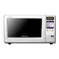
16
R-763 -
PROCEDURE
LETTER
M TOUCH CONTROL PANEL ASSEMBLY TEST
COMPONENT TEST
TEST PROCEDURES
If the display fails to clear when the STOP key is
depressed, first verify the lead wire harness is
making good contact, verify that the door sensing
switch (stop switch) operates properly; that is the
contacts are closed when the door is closed and
open when the door is open. If the door sensing
switch (stop switch) is good, disconnect the lead
wire harness that connects the switch unit to the
display unit and make sure the door sensing switch
is closed (either close the door or short the door
sensing switch connector). Use the Switch unit
matrix indicated on the switch unit circuit and place
a jumper wire between the pins that correspond to
the STOP key making momentary contact. If the
display unit responds by clearing with a beep the
switch unit is faulty and must be replaced. If the
display unit does not respond, it is a faulty and must
be replaced. If a specific key does not respond, the
above method may be used (after clearing the
display unit) to determine if the display unit or switch
unit is at fault.
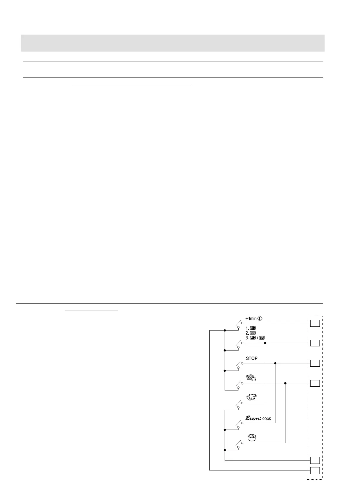
N SWITCH UNIT TEST
1
2
3
4
5
6
SW1
CN - G
SW2
SW3
SW4
SW5
SW6
SW7
The touch control panel consists of circuits including semiconductors such as LSI, ICs, etc. Therefore,
unlike conventional microwave ovens, proper maintenance cannot be performed with only a voltmeter
and ohmmeter.
In this service manual, the touch control panel assembly is divided into two units, Control Unit and Switch
Unit, and troubleshooting by unit replacement is described according to the symptoms indicated.
1. Switch Unit. Note : Check switch unit lead wire harness connection before replacement.
The following symptoms indicate a defective switch unit. Replace the switch unit.
a) When touching the keys, a certain key produces no signal at all.
b) When touching a key, two figures or more are displayed.
c) When touching the keys, sometimes a key produces no signal.
2. Control Unit
The following symptoms indicate a defective control unit. Before replacing the control unit,
perform the Switch unit test (Procedure N) to determine if control unit is faulty.
2-1 In connection with keys.
a) When touching the keys, a certain group of keys do not produce a signal.
b) When touching the keys, no keys produce a signal.
2-2 In connection with indicators
a) At a certain digit, all or some dots do not light up.
b) At a certain digit, brightness is low.
c) Only one indicator does not light.
d) The corresponding dots of all digits do not light up; or they continue to light up.
e) Wrong figure appears.
f) A certain group of indicators do not light up.
g) The figure of all digits flicker.
2-3 Other possible problems caused by defective control unit.
a) Buzzer does not sound or continues to sound.
b) Clock does not operate properly.
c) Cooking is not possible.