Do you have a question about the Sharp R-772WM and is the answer not in the manual?
This document describes the SHARP R-772(W)M/ R-772(G)M microwave oven, outlining its functions, technical specifications, usage, and maintenance.
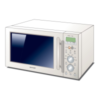
The SHARP R-772(W)M/ R-772(G)M is a microwave oven designed for various cooking tasks, including microwave, grill, oven, and dual (combination) cooking. It features a control panel for selecting cooking modes, setting times, and adjusting power levels. The oven is equipped with a turntable motor for even cooking, a fan motor for ventilation, and heating elements for grill and oven functions. Safety features include door interlock switches, thermal cut-outs, and a fuse to prevent electrical hazards.
Door Open Mechanism: The door is opened by pushing a button on the control panel, which activates an open lever to release the latch heads.
Monitored Latch Switch: This switch ensures that the oven is inoperative if the door is open. Its contacts (COM-NO) close when the door is closed and open when the door is open.
Stop Switch: Similar to the monitored latch switch, this switch also has contacts (COM-NO) that close when the door is closed and open when the door is open.
Monitor Switch: This switch is activated by the upper latch head when the door is closed. It's designed to blow fuse F8A if the monitored latch switch fails to open when the door is opened, preventing oven operation.
Fuses (15A 250V and F8A 250V): These fuses protect against short circuits and electrical hazards. F8A specifically blows if the monitored latch switch remains closed with the door open, or if components like the asymmetric rectifier, H.V. rectifier, H.V. wire harness, H.V. capacitor, magnetron, or secondary winding of the high voltage transformer are shorted.
T/C Transformer: Converts AC line voltage to low voltage to power the control unit.
Thermal Cut-Out 125°C (MG): Protects the magnetron from overheating. It opens if the temperature exceeds 125°C due to fan motor interruption or blocked ventilation, stopping magnetron operation.
Thermal Cut-Out 150°C (OVEN): Protects the oven from overheating during grill, oven, or dual cooking. It opens if the temperature exceeds 150°C due to fan motor interruption, blocked air inlet, or obstructed ventilation, switching off all electrical parts. It closes again when the temperature cools to 130°C.
Asymmetric Rectifier: A solid-state device that prevents current flow in both directions and protects the high voltage transformer by blowing fuse F8A if the high voltage rectifier shorts. It has two diodes, D1 (rated peak reverse voltage 6 KV) and D2 (rated peak reverse voltage 1.7 KV).
Noise Filter: Prevents radio frequency interference from flowing back into the power circuit.
Turntable Motor: Rotates the turntable for even cooking.
Fan Motor: A blade-driven motor that circulates cool air, cools the magnetron, and exhausts steam and vapors from the oven.
Top Grill Heating Element: Provides heat for the top grill function.
Bottom Grill Heating Element: Provides heat for the bottom grill function.
Oven Cooking System: Food is cooked by top and bottom heating elements. The temperature is controlled by the control unit. Heating elements are de-energized when the target temperature is reached and re-energized when the temperature drops below the target.
Fire Sensing Feature: Stops oven operation if a fire is detected. A thermistor measures the temperature across the measurement circuit. If the temperature rises rapidly, the oven stops.
Power Requirements: 230 - 240 Volts / 50 Hertz / Single phase, 3 wire earthed. Power Consumption:
The oven offers a variety of cooking modes and controls:
Control Panel: Features a display, oven lamp, grill heating element (top grill), door opening button, waveguide cover, oven cavity, turntable, and turntable motor shaft. Indicators: COOK indicator (showing oven in operation), TOP GRILL indicator, BOTTOM GRILL indicator, MICROWAVE indicator, WEIGHT indicators, and DEFROST indicator. Digital Display: Shows cooking progress, time, and power level. Time Keys: Used to select cooking time (10min, 1min, 10sec). Breakfast Key: For cooking breakfast items. Pizza Key: For cooking pizza. Auto Cook Key: For automatic cooking functions. Weight Keys: For weight-based cooking. Oven (°C) Key: To select oven temperature. Microwave Power Level Key: To select microwave power level. Stop/Clear Key: To stop a program, cancel a program, or turn off the oven. Start/Auto Minute Key: To start a program or add cooking time in multiples of 1 minute. Timer Key: To set the timer. Weight Conversion Key: For weight conversion.
Operation Sequence: The oven operates through various sequences depending on the selected cooking mode. For example, in microwave cooking, the magnetron generates microwave energy, while in grill cooking, the top and/or bottom heating elements are activated. Dual cooking combines microwave and grill functions. The control unit manages the relays (RY1-RY6) to activate the appropriate components (magnetron, heating elements, fan motor, turntable motor) based on the selected program.
Power Setting: The power setting for top heating, bottom heating, and fan motor in Oven cooking and preheating modes is 100%.
ON/OFF Time Ratio: In grill, oven, or dual cooking, components operate within a 48-second time base. The ON/OFF time ratio varies with the power output. For example, 100% power means 48 seconds ON and 0 seconds OFF, while 10% power means 8 seconds ON and 40 seconds OFF.
Limitations of Power Output in Manual Operation: After a specified cooking time, the power output is automatically reduced to protect the oven door from overheating. This limitation is not applied in automatic operations, or if the stop key is touched or the door is opened during cooking.
Automatic Cooking: Functions like PIZZA, BREAKFAST, INSTANT COOK, AUTO COOK, and AUTO DEFROST automatically determine the correct cooking mode, time, and temperature.
General Information: The appliance must be earthed. Wiring colors are green-and-yellow (earth), blue (neutral), and brown (live).
Servicing Precautions:
Troubleshooting Guide: A table is provided to diagnose problems based on symptoms and possible causes, linking them to specific components.
Test Procedures: Detailed procedures are outlined for testing various components:
Component Replacement and Adjustment Procedure:
Printed Wiring Board (PWB) and CPU Unit Circuit: Detailed diagrams are provided for the power unit circuit and CPU unit circuit, showing connections and components.
Parts List: Comprehensive lists of electric parts, cabinet parts, control panel parts, oven parts, door parts, miscellaneous/packing and accessories, and screws/nuts/washers are provided with part numbers, descriptions, and quantities.
| Brand | Sharp |
|---|---|
| Model | R-772WM |
| Category | Microwave Oven |
| Language | English |