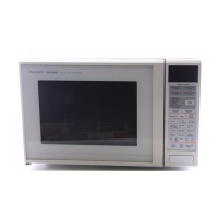
R-7N76(W)M
R-7N76(B)M
15
Temperature of Temperature of Indication of
"ON" condition "OFF" condition ohmmeter
Parts Name (closed circuit). (open circuit). (When room
(˚C) (˚C) temperature is
approx. 20˚C.)
Thermal cut-out This is not resetable Above 170˚C Closed circuit
170˚C type.
Thermal cut-out This is not resetable Above 125˚C Closed circuit
125˚C type
Thermal cut-out Below 170˚C Above 190˚C Closed circuit.
190˚C
CARRY OUT 3D CHECKS
Disconnect the leads from the terminals of the thermal cut-out. Then using an ohmmeter, make a continuity
test across the two terminals as described in the below.
If incorrect readings are obtained, replace the motor.
CARRY OUT
4R CHECKS
TEST PROCEDURES (CONT'D)
PROCEDURE
LETTER
G THERMAL CUT-OUT TEST
COMPONENT TEST
CARRY OUT 4R CHECKS
Table: Thermal Cut-out Test
If incorrect readings are obtained, replace the thermal cut-out.
An open circuit thermal cut-out (MG) indicates that the magnetron has overheated, this may be due to
resistricted ventilation, cooling fan failure.
An open circuit thermal cut-out (OVEN) indicates that the oven cavity has overheated, this may be due
to no load operation.
An open circuit thermal cut-out (CONV.) indicates that the convection fan motor winding has overheated,
this may be due to resisted ventilation or locked cooling fan or locked convection fan motor.
H MOTOR WINDING TEST
Table: Resistance of Motor
Motors Resistance
Fan motor Approximately 197 Ω
Turntable motor Approximately 16 kΩ
Convection fan motor Approximately 164 Ω
Damper motor Approximately 16 kΩ
CARRY OUT 3D CHECKS
Disconnect the leads from the motor. Using an ohmmeter, check the resistance between the two terminals
as described in the table below.
I NOISE FILTER TEST
CARRY OUT 3D CHECKS
Disconnect the leads from the terminals of noise filter.
Using an ohmmeter, check between the terminals as
described in the following table.
MEASURING POINTS INDICATION OF OHMMETER
Between N and L Approx. 680 kΩ
Between terminal N and WHITE Short circuit
Between terminal L and ORG Short circuit
L (min) Cx ± 20% Cy ± 20%
1.0mH 0.22µF 4700pF
If incorrect readings are absorbed, replace the noise filter unit.
CARRY OUT
4R CHECKS
R1: 10 MΩ ± 20%
R2 : 680 kΩ ± 20%
Cx
Cy
R2
R1
L
L
WHT
RED
13A
F8A
N
L