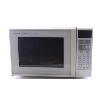
R-7N76(W)M
R-7N76(B)M
24
Pin No. Signal I/O Description
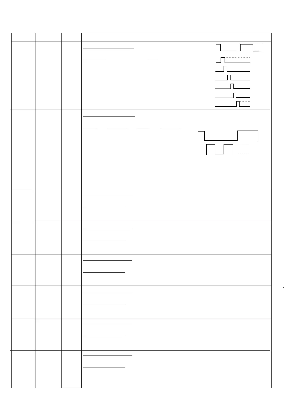
37-42 P23-P16 OUT Digit selection signal.
The relation between digit signal and digit are as follows:
Digit signal digit
P23 ........................................... 1st.
P22 .......................................... 2nd.
P21 ...........................................3rd.
P20 ........................................... 4th.
P17 ........................................... 5th.
P16 ........................................... 6th.
Normally, one pulse is output in every ß period,
and input to the Fluorescent Display.
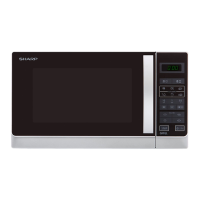
43-45 P15-P13 OUT Segment data signals.
The relationship between signals and indicators are as follows:
Signal Segment Signal Segment
P15 ............... LB P06 ...................f
P14 .............. UB P05 ..................g
P13 ................. a P04 .................. c
P12 ................. h P03 ..................e
P11 ...................j P02 ..................p
P10 ..................k P01 ..................n
P07 ................. b P00 ..................d
Refer to the touch control panel circuit for the relationship between signals and indicators.
Normally, one pulse is output in every synchronized signal (ß) period, and input to the anode
of the Fluorescent Display.
46 P12 OUT Segment data signal.
Signal similar to P15.
Key strobe signal.
Signal applied to touch-key section. A pulse signal is input to P24-P27 terminal while one
of G3 line keys on key matrix is touched.
47 P11 OUT Segment data signal.
Signal similar to P15.
Key strobe signal.
Signal applied to touch-key section. A pulse signal is input to P24-P27 terminal while one
of G4 line keys on key matrix is touched.
48 P10 OUT Segment data signal.
Signal similar to P15.
Key strobe signal.
Signal applied to touch-key section. A pulse signal is input to P24-P27 terminal while one
of G5 line keys on key matrix is touched.
49 P07 OUT Segment data signal.
Signal similar to P15.
Key strobe signal.
Signal applied to touch-key section. A pulse signal is input to P24-P27 terminal while one
of G6 line keys on key matrix is touched.
50 P06 OUT Segment data signal.
Signal similar to P15.
Key strobe signal.
Signal applied to touch-key section. A pulse signal is input to P24-P27 terminal while one
of G7 line keys on key matrix is touched.
51 P05 OUT Segment data signal.
Signal similar to P15.
Key strobe signal.
Signal applied to touch-key section. A pulse signal is input to P24-P27 terminal while one
of G8 line keys on key matrix is touched.
ß(50Hz)
GND
VP
H
L
GND
VP
ß(50Hz)
P23
P22
P21
P20
P17
P16
GND
VP