R-9320
R-9450
DESCRIPTION AND FUNCTION OF COMPONENTS
OVEN LAMP
The oven cavity lamp illuminate the interior of the oven so
that the food being cooked can be examined visually through
the door window without having to open the door.
FAN MOTOR
The fan motor drives a blade which draws cooling air through
the oven base.
This cooling air is directed through the air
vanes surrounding the magnetron and cools the magnetron
assembly. Most of the air is then exhausted directly through
the back vents. However, a portion of this air is channeled
through the cavity to remove steam and vapors given off from
the heating foods.
It is then exhausted at the top of the oven
cavity into a condensation compartment.
TURNTABLE MOTOR
The turntable motor rotates the turntable located on the
bottom of oven cavity, so that It works to cook the foods on
the turntable evenly.
COOK RELAY
The coil of the cook reiay is energrzed oy the control unit,
thereby closing its
contacts which provide a current path to
the power transformer.
The cook relay is activated by 18 volts D.C. supplied from the
control unit.
STOP SWITCH
The stop switch is provided on the open device of the control
panel assembly and activated by the open button. When the
open button is depressed while the oven is in cook cycle, the
stop switch contacts open to de-energize the control relay and
cook relay circuits and causes cook time counting-down to
pause.
TEMP. FUSE
The temp. fuse located on the magnetron is designed to pre-
vent damage to the magnetron if an overheated condition
develops in the tube due to cooling fan failure, obstructed air
ducts, dirty or blocked air intake, etc.
Under normal operation, the temp. fuse remains closed.
However, when abnormally high temperatures within the mag-
netron approach a critical level, the temp. fuse will open and
interrupt the circuit to the oven, causing it to shut down.
This is a fuse and it does not reset.
TEMPERATURE PROBE (R-9450 ONLY)
The temperature probe assembly consists of a thermistor
element, shield case, wire lead and plug. The thermistor in the
probe tip is a negative temperature coefficient type.
Nominal resistance of the probe at room temperature (25°C)
is approx. 42.6 to 58.0 kilo-ohms. As the temperature of the
probe increases, the resistance decreases as shown in the
following chart.
The change in probe resistance is applied to the printed wiring
board.
THERMISTOR
TEMPERATURE
25°C
32°C
38°C
66°C
93k
98°C
PROBE
RESISTANCE
(APPROX.)
42.6 - 58.0 kfi
31.8 - 42.8 kfi
24.9 - 33.2 kL?
8.5 - 10.9 ka
3.7 - 4.1 k!J
3.2 - 3.9 kfi
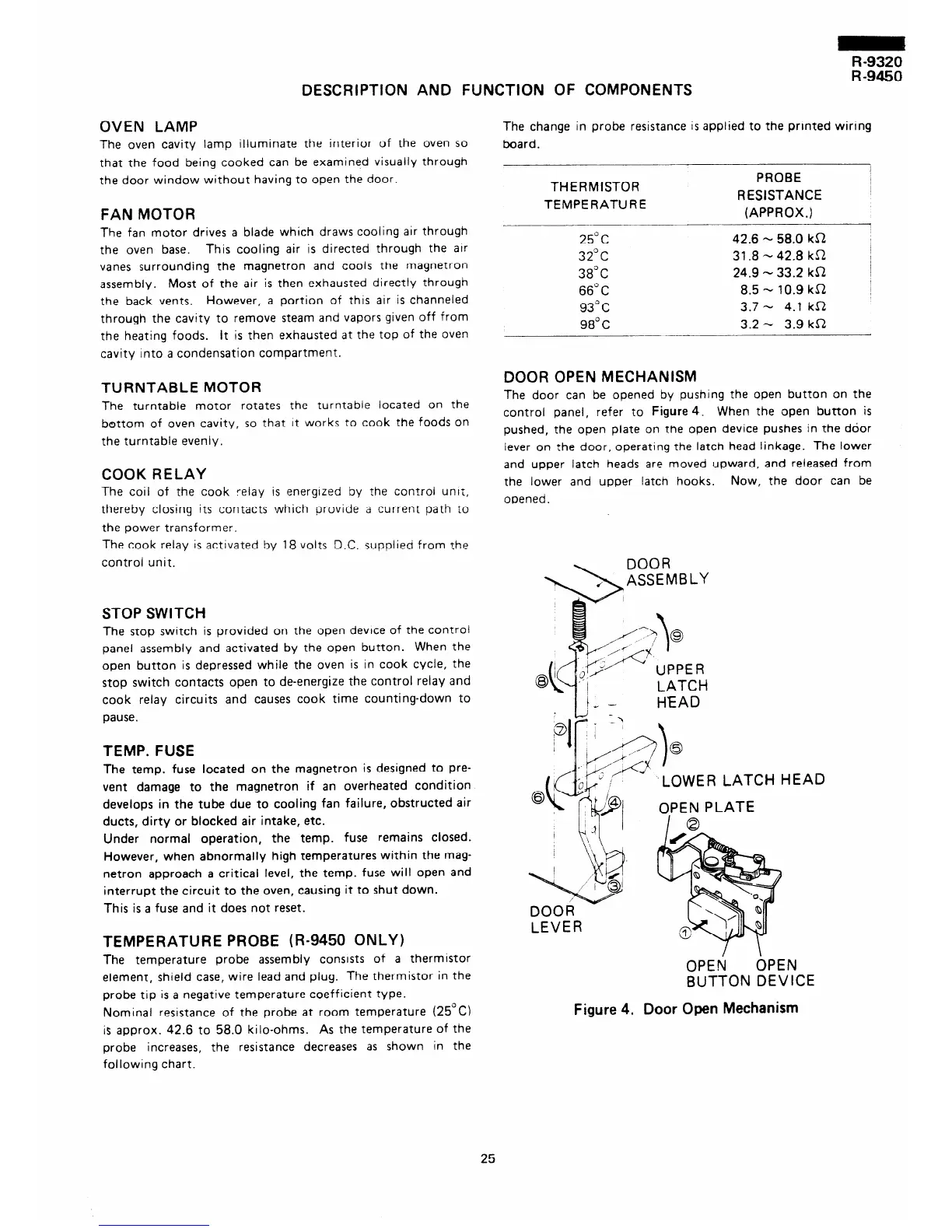
DOOR OPEN MECHANISM
The door can be opened by pushing the open button on the
control panel, refer to Figure 4. When the open button is
pushed, the open plate on the open device pushes in the door
lever on the door, operating the latch head linkage. The lower
and upper latch heads are moved upward, and released from
the lower and upper latch hooks.
Now, the door can be
oDened.
LATCH
HEAD
LOWER LATCH H
EAD
OPEN
OPEN
SUTTON DEVICE
Figure 4. Door Open Mechanism
25