R-9320
R-9450
POWER TRANSFORMER
The transformer consists of three windings: primary,
filament and high voltage.
During a cook cycle, the 240 volts A.C. applied to the
primary winding of the transformer through the cook relay
contacts is converted to 3.45 volts AC. on the filament
winding and approximately 2350 volts A.C. on the high
voltage winding. The 3.45 volts A.C. voltage heats the
magnetron filament. This causes the tube cathode to
readily emit the electrons necessary for tube conduction
whenever the negative 4000 D.C. voltage is applied to the
cathode.
The 2350 volts A.C. voltage is fed to the voltage doubler
circuit.
VOLTAGE DOUBLER CIRCUIT
The voltage doubler circuit consists of a rectifier and
a capacitor. The 2350 volts A.C. from the high voltage
winding of the power transformer is applied to the voltage
doubler circuit, where it is rectified and converted to
approximately 4000 volts negative D.C. needed for magne-
tron operation.
Rectifier: The rectifier is solid state device that allows
current flow in one direction, but prevents current flow in
the opposite direction.
This acts as rectifier changing
alternating current into pulsating D.C.
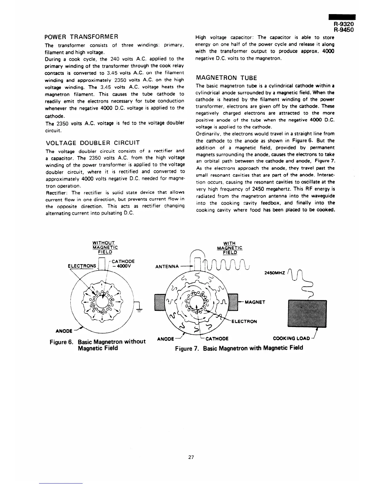
WITHOUT
MAGNETIC
FIELD
; 7 CATHODE
Figure 6. Basic Magnetron without
Magnetic Field
High voltage capacitor: The capacitor is able to store
energy on one half of the power cycle and release it along
with the transformer output to produce approx. 4ooO
negative D.C. volts to the magnetron.
MAGNETRON TUBE
The basic magnetron tube is a cylindrical cathode within a
cylindrical anode surrounded by a magnetic field. When the
cathode is heated by the filament winding of the power
transformer, electrons are given off by the cathode. These
negatively charged electrons are attracted to the more
positive anode of the tube when the negative 4000 D.C.
voltage is applied to the cathode.
Ordinarily, the electrons would travel in a straight line from
the cathode to the anode as shown in Figure 6. But the
addition of a magnetic field, provided by permanent
magnets surrounding the anode, causes the electrons to take
an orbital path between the cathode and anode, Figure 7.
As the electrons approach the anode, they travel past the
small resonant cavities that are part of the anode. Interac-
tion occurs, causing the resonant cavities to oscillate at the
very high frequency of 2450 megahertz. This RF energy is
radiated from the magnetron antenna into the waveguide
into the cooking
cavity feedbox, and finally into the
cooking cavity where food has been placed to be cooked.
WITH
MAGNETIC
f-7 -
FIELD
I-’
1 1 i 47 n ,n
ANODE /
i CATHODE
COOKING LOAD’
Figure 7. Basic Magnetron with Magnetic Field
27