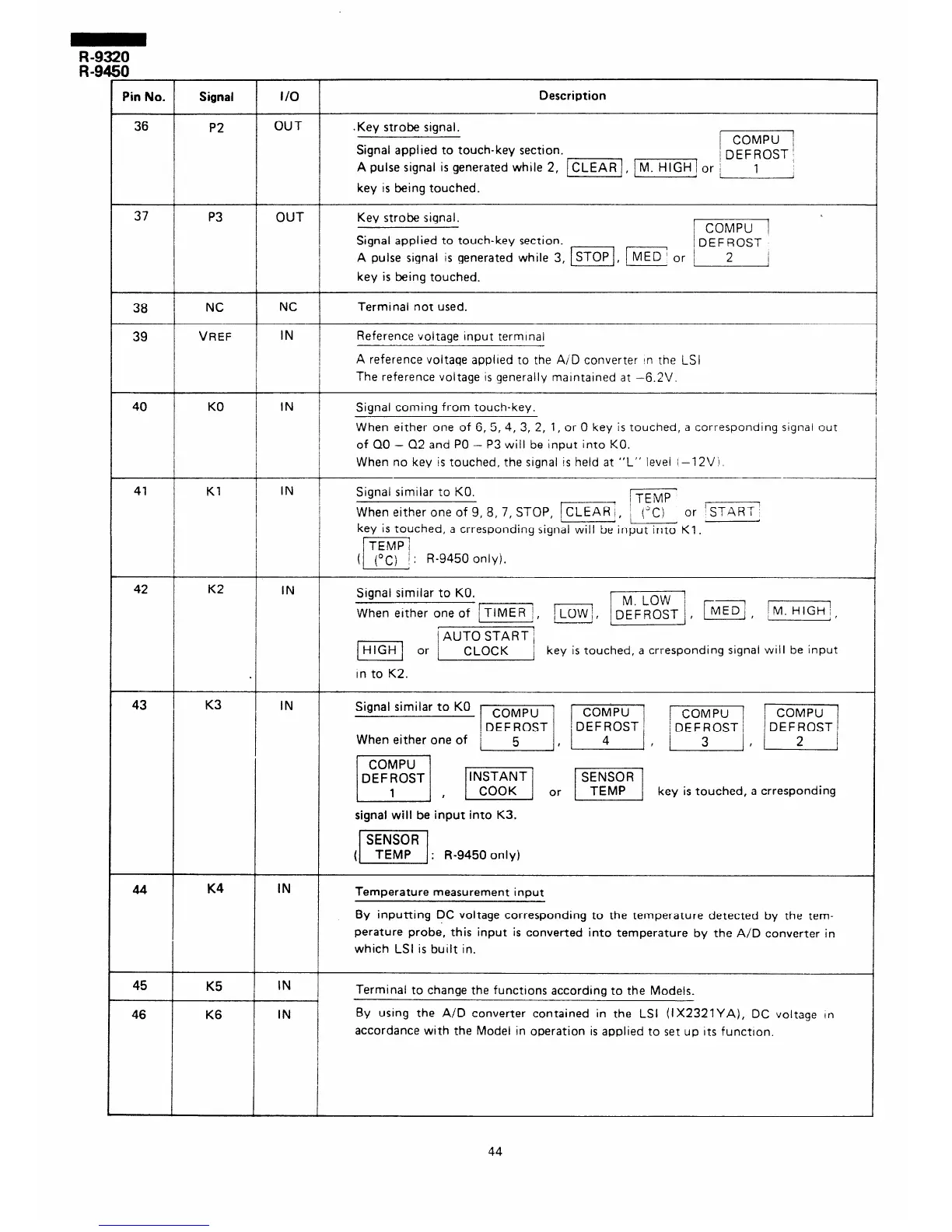
In No.
Signal
36
P2
l/O
OUT
Description
.Key strobe signal.
Signal applied to touch-key section.
/
j DEFROST /
A pulse signal is generated while 2, m, m or ;
: 1
i
key is being touched.
37
P3
OUT Key strobe signal.
Signal applied to touch-key section.
A pulse signal is generated while 3, ISToP IMED] or [
/
key is being touched.
38
NC
39
VREF
NC
IN
Terminal not used.
Reference voltage input terminal
A reference voltage applred to the A/D converter In the LSI
The reference voltage IS generally maintained at -6.2V.
40 KO
IN I
Signal coming from touch-key.
When either one of 6, 5, 4, 3, 2, 1, or 0 key is touched, a corresponding signal out
of QO - Q2 and PO - P3 will be input into KO.
When no key is touched, the signal is held at “L” level i-l 2Vi.
41
Kl
IN
Signal similar to KO.
I
j TEMP
When either one of 9, 8, 7, STOP, (CLEAR;, i (“C)
or ‘START
key is touched, a crresponding signal will be input into KI.
; : R-9450 only).
42
K2
IN
Signal similar to KO.
When either one of m, j,
I
1
b=-j , j M. HIGH;,
key is touched, a crresponding signal will be input
in to K2.
43 K3
IN
Signal similar to KO
When either one of
,
F] , E! or m] key is touched, a crresponding
signal will be input into K3.
: R-9450 only)
K4
IN
Temperature measurement input
By inputting DC voltage corresponding to the temperature detected by the tem-
perature probe, this input is converted into temperature by the A/D converter in
which LSI is built in.
45
K5
46 K6
IN
IN
Terminal to change the functions according to the Models.
By using the A/D converter contained in the LSI (IX2321YA), DC voltage In
accordance with the Model in operation is applied to set up Its function.
44