R-9320
R-9450
BUZZER CIRCUIT
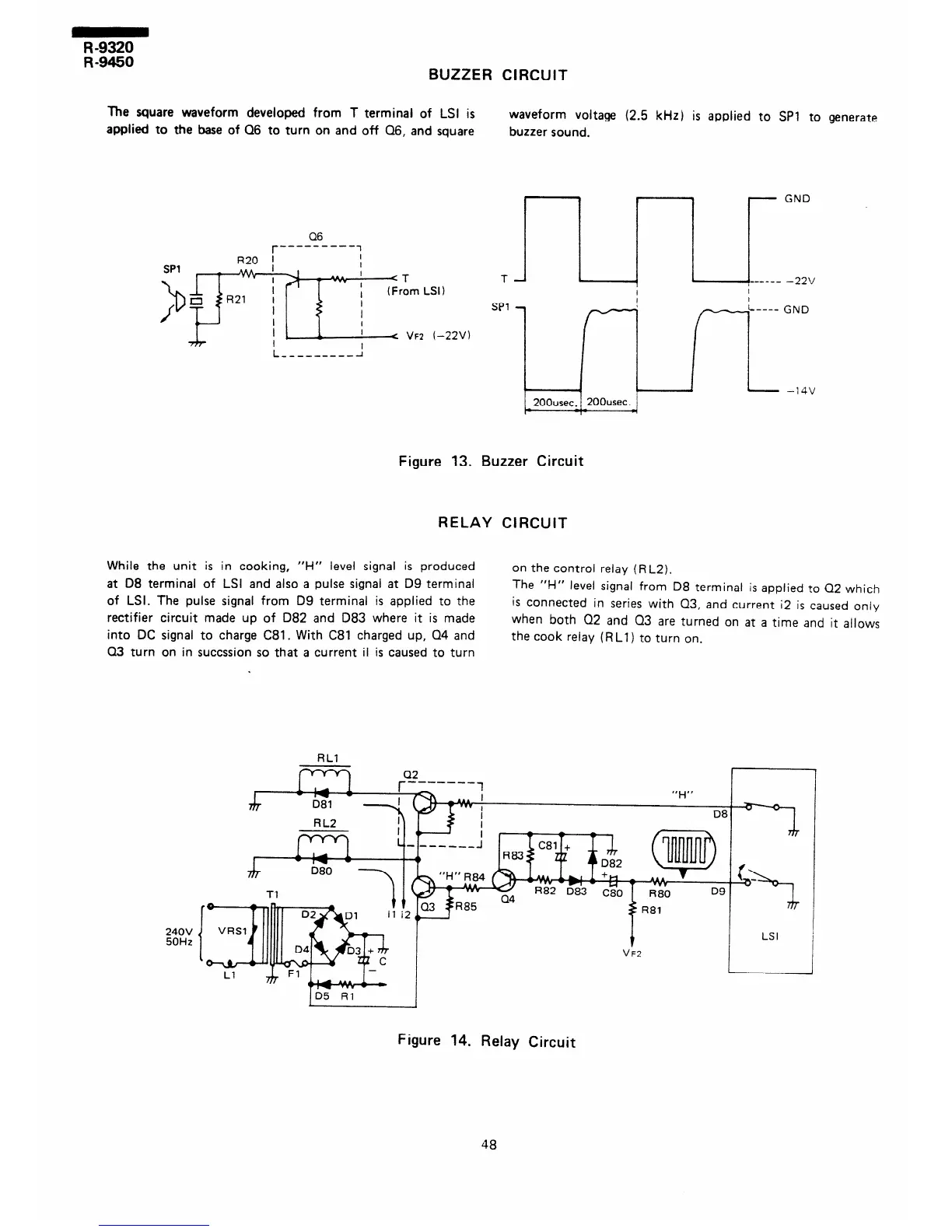
The square waveform developed from T terminai of LSI is
applied to the base of Q6 to turn on and off Q6, and square
waveform voltage (2.5 kHz) is applied to SPl to generate
buzzer sound.
Cl6
r
---------
1
T
SPl
GND
GND
200usec. 1 200usec.
I
Figure 13. Buzzer Circuit
RELAY CIRCUIT
While the unit is in cooking, “H” level signal is produced
on the control relay (R L2).
at 08 terminal of LSI and also a pulse signal at D9 terminal
The “f-i” level signal from D8 terminal is applied to Q2 which
of LSI. The pulse signal from D9 terminal is applied to the
rectifier circuit made up of 082 and 083 where it is made
is connected in series with 03, and current i2 is caused only
when both 02 and Q3 are turned on at a time and it allows
into DC signal to charge C81. With C81 charged up, Q4 and
Q3 turn on in succssion so that a current il is caused to turn
the cook relay (RLl) to turn on.
240V
50Hz
RLl
I
Tl
i
ID5 Rl
I
Figure 14. Relay Circuit
48