20
TEST PROCEDURES
PROCEDURE
LETTER
COMPONENT TEST
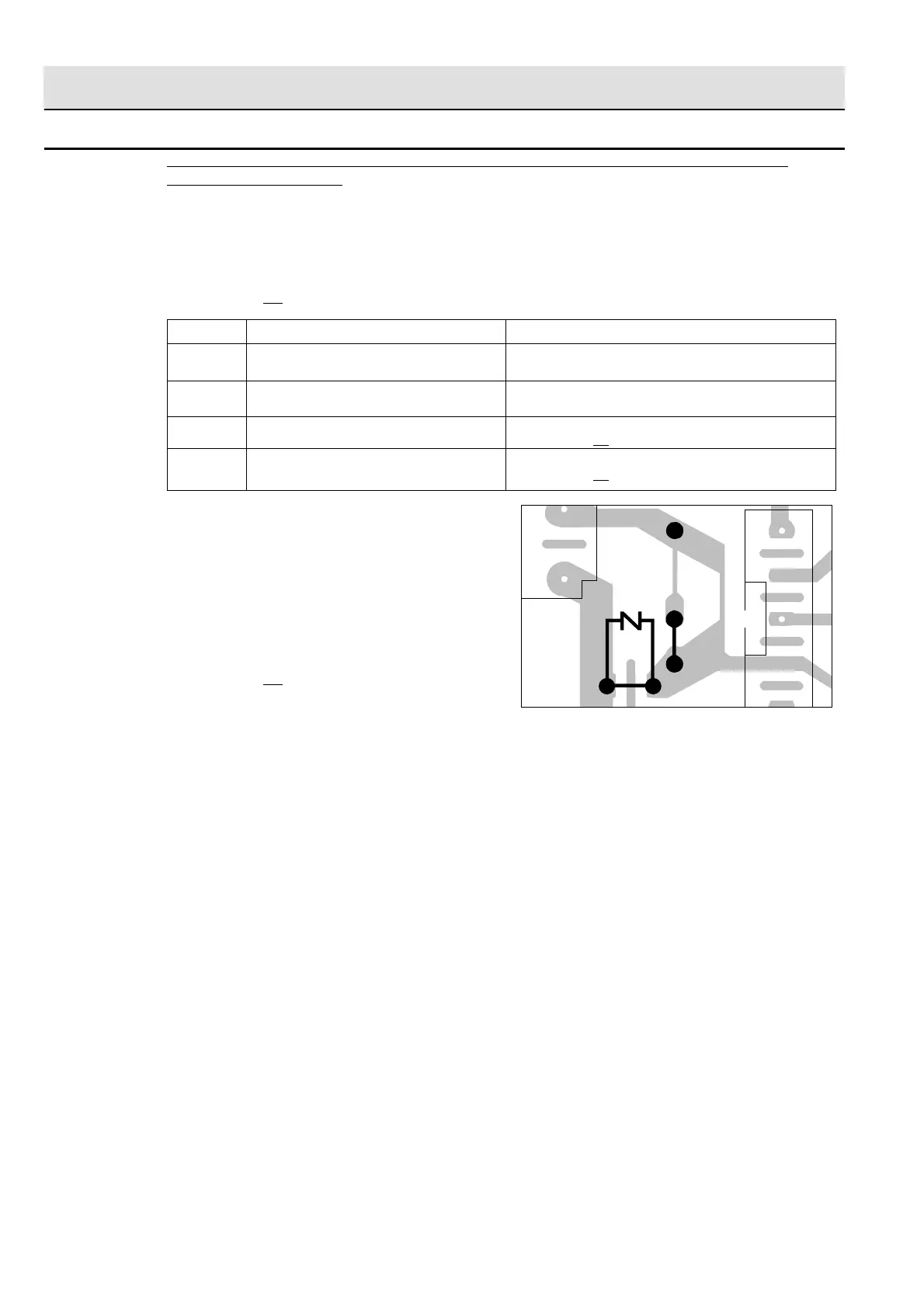
To protect the electronic circuits, this model is provided with a fine foil pattern added to the input circuit
on the PWB, this foil pattern acts as a fuse. If the foil pattern is open, follow the troubleshooting guide
given below for repair.
Problem: POWER ON, indicator does not light up.
CARRY OUT
3D CHECKS.
STEPS OCCURRENCE CAUSE OR CORRECTION
1 The rated AC voltage is not present between Check supply voltage and oven power cord.
Pin Nos. 1 and 3 of the 4-pin connector (E).
2 The rated AC voltage is present at primary Low voltage transformer or secondary circuit defective.
side of low voltage transformer. Check and repair.
3 Only pattern at "a" is broken. *Insert jumper wire J1 and solder.
(CARRY OUT 3D CHECKS BEFORE REPAIR)
4 Pattern at "a" and "b" are broken. *Insert the coil RCILF2003YAZZ between "c" and "d".
(CARRY OUT 3D CHECKS BEFORE REPAIR)
NOTE: *At the time of these repairs, make a visual
inspection of the varistor for burning dam-
age and examine the transformer with
tester for the presence of layer short cir-
cuit (check primary coil resistance).
If any abnormal condition is detected,
replace the defective parts.
CARRY OUT 4R CHECKS.
P PROCEDURES TO BE TAKEN WHEN THE FOIL PATTERN ON THE PRINTED WIRING
BOARD (PWB) IS OPEN
(J1)
(J2)
9
1
7
CN - E
CN - A
VRS1
a
c
d
b