22
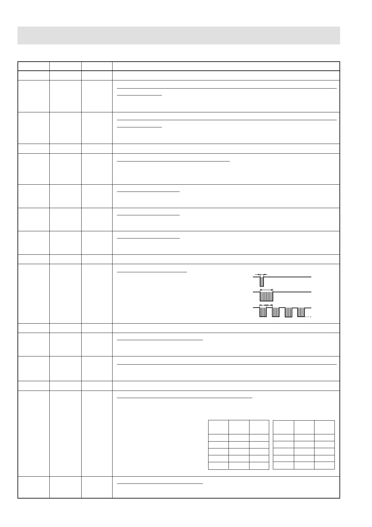
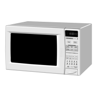
DESCRIPTION OF LSI
LSI(IXA036DR)
The I/O signal of the LSI(IXA036DR) are detailed in the following table.
Pin No. Signal I/O Description
1 AN0 IN Terminal not used.
2 P77 OUT
Timing signal output terminal for temperature measurement(OVEN
THERMISTOR).
"H" level (GND) : Thermistor OPEN timing.
"L" level (-5V) : Temperature measuring timing. (Convection cooking)
3 P76 OUT Timing signal output terminal for temperature measurement(OVEN
THERMISTOR).
"H" level (GND) : Thermistor OPEN timing.
"L" level (-5V) : Temperature measuring timing. (Convection cooking)
4-5 P75-P74 OUT Terminal not used.
6 P73 IN Signal coming from touch tact switch.
When any one of J-3 line tact switches on tact switch matrix is touched, a
corresponding signal from P14, P15, P16 and P17 will be input into P73. When no
tact switch is touched, the signal is held at "L" level.
7 P72 IN Signal similar to P73.
When any one of J-4 line tact switches on tact switch matrix is touched, a
corresponding signal will be input into P72.
8 P71 IN Signal similar to P73.
When any one of J-7 line tact switches on tact switch matrix is touched, a
corresponding signal will be input into P71.
9 P70 IN Signal similar to P73.
When any one of J-8 line tact switches on tact switch matrix is touched, a
corresponding signal will be input into P70.
10-11 P57-P56 OUT Terminal not used.
12 P55 OUT Signal to sound buzzer.
A: Tact switch touch sound.
B: Completion sound.
C: When the temperature of the oven
cavity reaches the preset
temperature in the preheating mode,
or when the preheating hold time (30
minutes) is elapsed.
13-17 P54-P50 OUT Terminal not used.
18 P47 IN Signal coming from encoder.
When the encoder is turned, the contacts of encoder make pulse signals. And
pulse signal is input into P47.
19 P46 IN Input signal which communicates the damper open/close information to LSI.
Damper opened; "H" level signal (0V:GND).
Damper closed; "L" level signal (-5V:VC).
20 P45 OUT Terminal not used.
21 P44 OUT Magnetron high-voltage circuit driving signal.
To turn on and off the cook relay
(RY2). In 100% operation, the
signals hold "L" level during
microwave cooking and "H" level
while not cooking. In other
cooking modes (70%, 50%, 30%,
10%) the signal turns to "H" level
and "L" level in repetition
according to the power level.
22 INT1 IN Signal coming from encoder.
Signal similar to P47. Pulse signals are input into INT1.
A
B
C
H: GND
L
0.12 sec
2.4 sec
1.2 sec
1.2 sec
ON/OFF time ratio in Mi-
cro cooking
(a. 32second time base)
ON/OFF time ratio in Mi-
cro cooking
(a. 48second time base)
MICRO ON OFF
COOK
100% 32 sec. 0 sec.
70% 24 sec. 8 sec.
50% 18 sec. 14 sec.
30% 12 sec. 20 sec.
10% 6 sec. 26 sec.
MICRO ON OFF
COOK
100% 48 sec. 0 sec.
70% 36 sec. 12 sec.
50% 26 sec. 22 sec.
30% 16 sec. 32 sec.
10% 8 sec. 40 sec.