ON
OFF
During
cooking
L
GND
H.
1 VCC IN Connected to GND.
2 VEE IN Anode (segment) of Fluorescent Display light-up voltage: -30V.
Vp voltage of power source circuit input.
3 AVSS IN Power source voltage: -5V.
VC voltage of power source circuit input.
4 VREF IN Reference voltage input terminal.
A reference voltage applied to the A/D converter in the LSI. Connected to
GND.(0V)
5-6 AN7-AN6 IN Terminal not used.
7-9 AN5-AN3 IN Heating constant compensation terminal.
10 AN2 IN Input signal which communicates the door open/close information to LSI.
Door closed; "H" level signal(0V).
Door opened; "L" level signal(-5V).
11 AN1 IN Input signal which communicates the damper open/close information to LSI.
Damper opened; "H" level signal(0V:GND).
Damper closed; "L" level signal(-5V).
12 AN0 IN Temperature measurement input: OVEN THERMISTOR.
By inputting DC voltage corresponding to the temperature detected by the
thermistor, this input is converted into temperature by the A/D converter built into
the LSI.
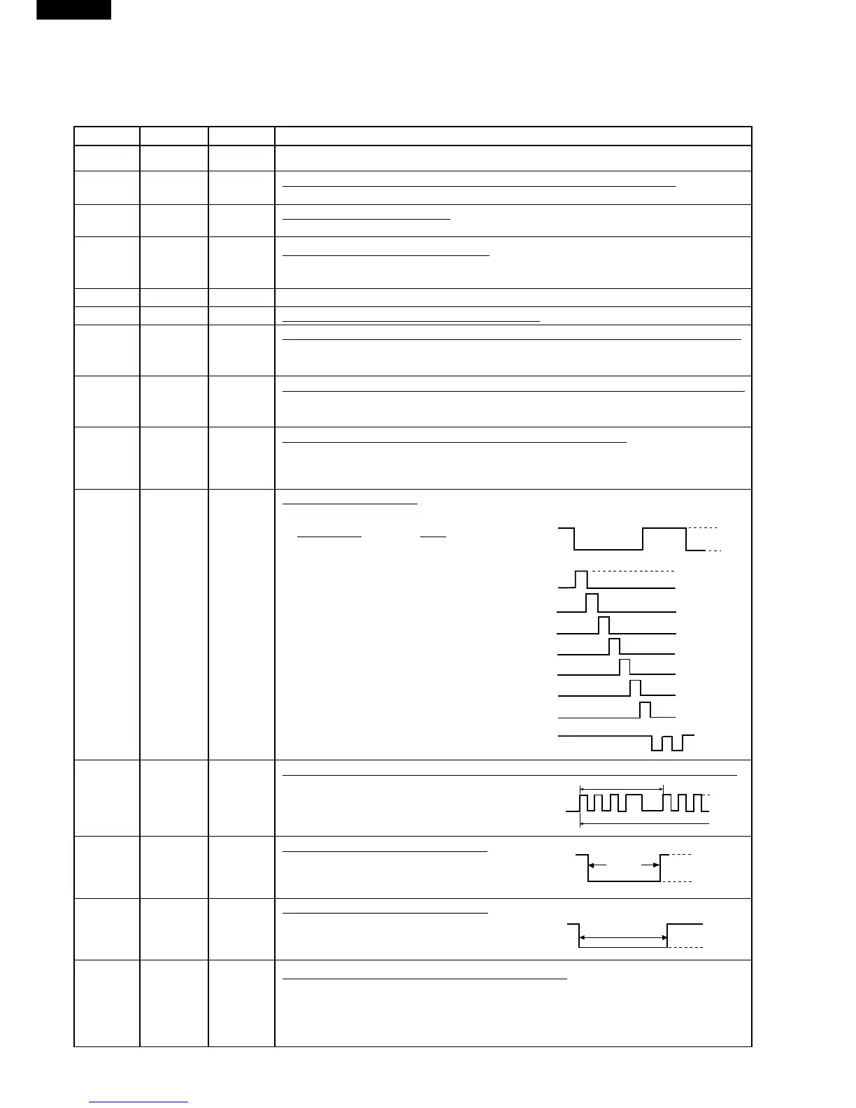
13 P55 OUT Digit selection signal.
The relationship between digit signal and digit are as follows;
Digit signal Digit
P03 ...........................1st.
P02 ..........................2nd.
P01 .......................... 3rd.
P00 ...........................4th.
P37 ...........................5th.
P36 .......................... 6th.
P35 .......................... 7th.
P55 .......................... 8th.
Normally, one pulse is output in every ß
period, and input to the grid of the
Fluorescent Display.
14 P54 OUT Oven lamp and turntable motor driving signal. (Square Waveform : 50Hz)
To turn on and off the shut-off
relay(RY1). The square waveform volt-
age is delivered to the relay(RY1) driv-
ing circuit.
15 P53 OUT Convection motor driving signal.
To turn on and off shut-off relay(RY5). "L"
level during CONVECTION and during
back up for GRILL; "H" level otherwise.
16 P52 OUT Cooling fan motor driving signal.
To turn on and off shut-off relay(RY6). "L"
level during both microwave and convec-
tion cooking; "H" level otherwise.
17 P51 OUT Magnetron high-voltage circuit driving signal.
To turn on and off the cook relay(RY2). In HIGH operation, the signals holds "L"
level during microwave cooking and "H" level while not cooking. In other cooking
modes (MED HIGH, MED, MED LOW, LOW) the signal turns to "H" level and "L"
level in repetition according to the power level.