R-950A
28
DOOR REPLACEMENT AND ADJUSTMENT
DOOR REPLACEMENT
1. Disconnect oven from power supply and remove outer
case. Remove turntable tray and roller stay from oven
cavity.
2. Remove three (3) screws holding lower oven hinge.
3. Remove lower oven hinge from oven cavity bottom flange.
4. Remove door assembly from upper oven hinge on the oven.
5. Door assembly is now free.
Note: When individual parts are replaced, refer to “Door
Disassembly”.
6. On re-installing door, insert the upper oven hinge into
the door hinge pin.
Then while holding door in place.
7. Make sure door is parallel with oven face lines (left and
upper side lines) and the door latch heads pass through
the latch holes correctly.
8. Insert the lower oven hinge into oven cavity bottom flange
and then engage the door hinge pin. Then secure the
lower oven hinge firmly with three (3) mounting screws.
Remove door assembly, refer to “Door Replacement”.
Replacement of door components are as follows:
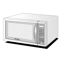
1. Place door assembly on a soft cloth with latches facing up.
Note: As the engaging part of choke cover and door
panel are provided at several places, do not force
any particular part.
2. Insert an putty knife (thickness of about 0.5mm) into the
gap between the choke cover and corner portion of
door panel as shown figure C-2 to free engaging parts.
3. Lift up choke cover.
4. Now choke cover is free from door panel.
CHOKE COVER
PUTTY KNIFE
FRONT
INSIDE
Upper
Lower
Bent
Door
Panel
Choke
cover
1 BENT
2 LIFT UP
Figure C-2. Door Disassembly
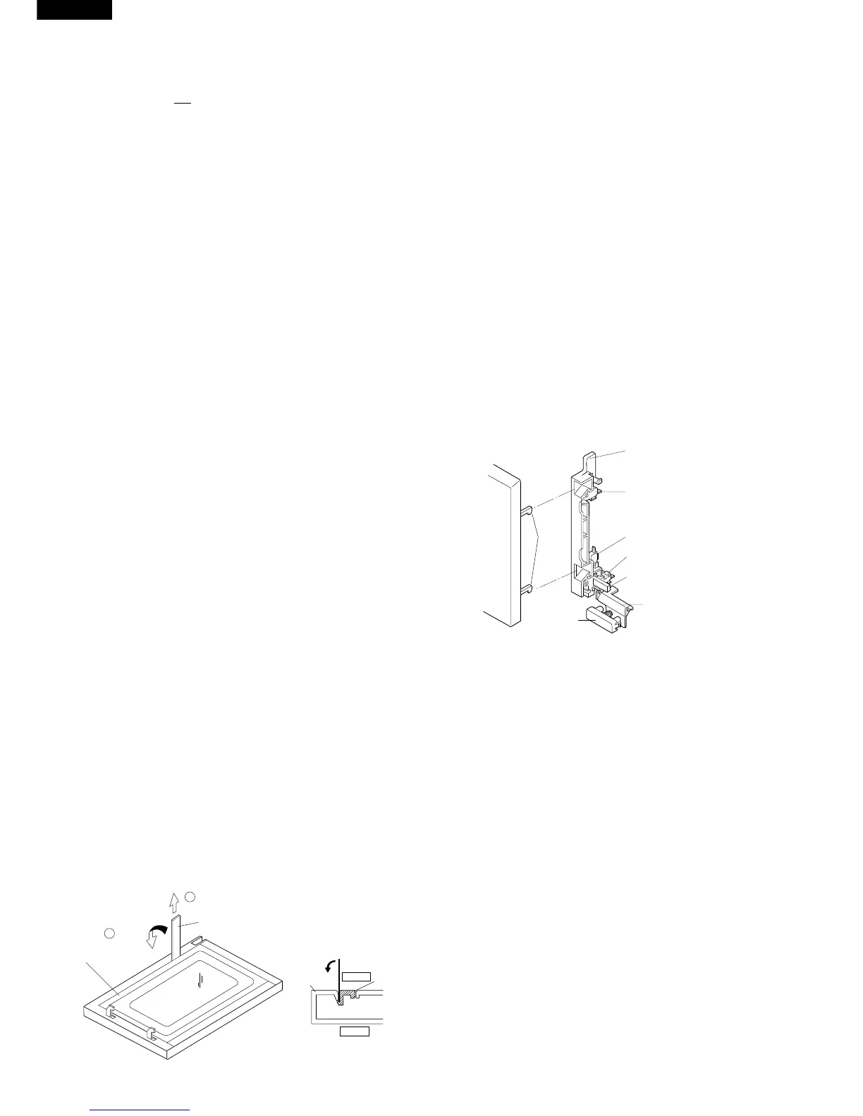
Re-install
1. Re-install switch lever and each switch in its place,
refer to Figure C-1.
2. Re-connect the wire leads to each switches and fuse
holder.
Refer to the pictorial diagram.
3. Secure the latch hook (with two (2) mounting screws)
to the oven flange.
4. Make sure that monitor switch is operating properly.
Refer to chapter “Test Procedure” and Adjustment
procedure.
1ST. LATCH SWITCH, 2ND. INTERLOCK RELAY CONTROL SWITCH AND MONITOR SWITCH REMOVAL
1. CARRY OUT 3D CHECKS.
2. Remove control panel assembly, refer to “Control
Panel Removal”.
3. Disconnect wire leads from each of the switches.
4. Remove two (2) screws holding latch hook to oven flange.
5. Remove latch hook assembly from oven flange.
6. Push downward on the one (1) stopper tabs holding
each of the switches place.
7. Switches are free.
At this time switch lever will be free, do not lose it.
If
1st. latch switch, 2nd. interlock relay control switch and
monitor switch
do not operate properly due to a mis-
adjustment, the following adjustment should be made.
1. Loosen the two (2) screws holding the latch hook to the
flange on the oven front face.
2.
With the door closed, adjust the latch hook by moving it
back and forth and then adjust the latch hook by moving it
back and forth. In and out play of the door allowed by the
latch hook should be less than 0.5 mm. The vertical
position of the latch hook should be adjusted so that the
1st. latch switch and 2nd. interlock relay control switch are
activated with the door closed. The horizontal position of
the latch hook should be adjusted so that the plunger of the
monitor switch is pressed with the door closed.
3. Secure the screws with washers firmly.
4. Now, make sure all switches operations. If each switch
has not been activated with the door closed, loose the
screws holding the latch hook to the oven cavity front
flange and adjust the latch hook position.
After the adjustment, make sure of the following:
1. The in and out play of the door remains less than 0.5
mm at latched position.
2. The
1st. latch switch and 2nd. interlock relay control switch
interrupt the circuit before the door can be opened.
3. The monitor switch contacts close when the door is
opened.
4. Re-install the outer case and check for microwave
leakage around the door with an approved microwave
survey meter. (Refer to Microwave Measurement
Procedure.)