SERVICE MANUAL
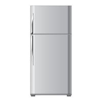
SJ-PT55R-HS
No.SY746SE55CRYFT
This document has been published to be used for
after sales service only.
The contents are subject to change without notice.
CHAPTER 1. SPECIFICATION
CHAPTER 2. DESIGNATION OF VARIOUS PARTS
[1] EXTERNAL DESCRIPTION........................... 2-1
[2] CONSTRUCTIONS........................................ 2-3
CHAPTER 3. DIMENSIONS
[1] OUTER DIMENSIONS AND
CLEARANCE ................................................. 3-1
[2] INNER DIMENSIONS .................................... 3-3
CHAPTER 4. LIST OF ELECTRICAL PARTS
[1] SJ-PT51R/PT55R .......................................... 4-1
[2] SJ-T51R/T55R ............................................... 4-1
CHAPTER 5. WIRING DIAGRAM
[1] WIRING DIAGRAM ........................................ 5-1
[2] ELECTRIC ACCESSORIES LAYOUT ........... 5-2
[3] CIRCUIT DIAGRAM....................................... 5-4
CHAPTER 6. FAILURE DIAGNOSIS
[1] OUTLINE OF CONTROL ............................... 6-1
[2] WHEN THE DEFROSTING FAILURE IS
DOUBTFUL(Only for SJ-PT51R/PT55R)........ 6-1
[3] RE-SETTING OF MICROCOMPUTER AT
POWER FAILURE.......................................... 6-1
[4] DIAGNOSIS METHOD OF FAILURE
AROUND PWB .............................................. 6-2
[5] CONVERSION TABLE BETWEEN TEM-
PERATURE AND RESISTANCE VALUE........6-3
CHAPTER 7. SELF-DIAGNOSIS MODE (Only for SJ-
PT51R/PT55R)
CHAPTER 8. MODE FOR DISPLAY (Only for SJ-
PT51R/PT55R)
CHAPTER 9. ASSEMBLING PROCEDURES OF
MAIN PARTS AND CAUTIONS
[1] FAN LOUVER AND E.V COVER ASSEM-
BLY ................................................................9-1
[2] R CONTOROL COVER ASSEMBLY (SJ-
PT51R/PT55R) ..............................................9-3
[3] R CONTOROL COVER ASSEMBLY (SJ-
T51R/T55R)...................................................9-5
[4] R SHOWER DUCT ASSEMBLY....................9-7
[5] DEFROST HEATER ASSEMBLY ..................9-8
CHAPTER 10. COOLING UNIT
[1] COOLING UNIT...........................................10-1
[2] LOCATION ..................................................10-2
Parts Guide
TopPage
CONTENTS
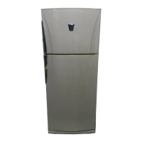
SJ-PT51R-HS
SJ-PT55R-HS
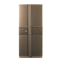
SJ-T51R-SL
SJ-T55R-SL
Refrigerator-freezer
MODELS
Refer to "HFC-134a COOLING UNIT" Service Manual for handling this refrigerant.
Refrigerant; HFC-134a