EasyManua.ls Logo

Sharp SJ-GF60X-T User Manual

Sharp SJ-GF60X-T
70 pages
To Next Page IconTo Next Page
Page #1 background imageLoading...
Page #1 background image
SERVICE MANUAL
This document has been published to be used for
after sales service only.
The contents are subject to change without notice.
Refrigerator-freezer
MODEL
SJ-GF60X-T
No.S0310SJF60XTFT
DESTINATION F
CONTENTS
Refer to "REFRIGERATING-CYCLE REPAIR MANUAL" for handling this refrigerant.
Refrigerant; R600a
[1] PRODUCT SPECIFICATIONS
1. SPECIFICATIONS ………………………… 2
2. ACCESSORIES …………………………… 2
3. AUTOMATIC ICE MAKING ……………… 3
[2] DESIGNATION OF VARIOUS PARTS
1. PART NAMES ……………………………… 4
2. INTERNAL STRUCTURE ………………… 5
3. FLOW OF COOL AIR ……………………… 6
4. TEMPERATURE DISTRIBUTION ………… 7
[3] DIMENSIONS
1.
OUTER DIMENSIONS AND CLEARANCE
…8
2. INNER DIMENSIONS ……………………… 9
[4] ELECTRICAL CIRCUIT DIAGRAMS …………10
1. WIRING DIAGRAM …………………………10
2. ELECTRIC ACCESSORIES LAYOUT …… 11
3.
PRECAUTIONS FOR USING LEAD-FREE SOLDER
……12
[5] ELECTRICAL SYSTEM SPECIFICATIONS 13
1. FUNCTIONAL PART SPECIFICATIONS …13
2. MODE FOR DISPLAY ……………………… 14
[6]
REFRIGERATION CYCLE SYSTEM SPECIFICATIONS
1. R600A PRECAUTIONS …………………… 15
2.
TABLE OF R600A CHARACTERISTICS
…15
3. REFRIGERATION CYCLE DIAGRAM ……15
4.
REPAIR OF THE REFRIGERATION CYCLE
…17
[7] TROUBLESHOOTING
1. SELF-DIAGNOSIS MODE ………………… 18
2.
FORCED STOPPING OF DOOR ALARM BUZZER
…22
3.
THERMISTOR CIRCUIT CHECK METHOD
…22
4.
INSPECTION FLOWCHART AND REPAIR ITEMS
…23
5.
PLASMACLUSTER OK/NG JUDGMENT
…25
[8] DISASSEMBLY/ASSEMBLY
1.
GENERAL DISASSEMBLY SEQUENCE
…26
2.
REFRIGERATOR COMPARTMENT DISASSEMBLY
…27
3. FREEZER COMPARTMENT/ICE
COMPARTMENT DISASSEMBLY ………29
4. HOW TO REMOVE OP. PWB ASS'Y ……31
5. HOW TO REMOVE TERMINAL BOX ……31
6. HOW TO INSTALL R-SUB PACKING ……32
7.
HOW TO INSTALL DUCT RT ASS'Y COVER
…33
8.
ADJUSTMENT OF R-DOOR (DOUBLE DOOR)
…34
9. MAIN PARTS ASSEMBLY …………………35
Parts Guide
Question and Answer IconNeed help?

Do you have a question about the Sharp SJ-GF60X-T and is the answer not in the manual?

Sharp SJ-GF60X-T Specifications

General IconGeneral
CategoryRefrigerator
Defrosting TypeAutomatic
Energy Efficiency ClassA++
Climate ClassSN-T
Noise Level39 dB
ColorBrown
Ice MakerYes
DeodorizerYes

Summary

Product Specifications

1. Specifications

Detailed technical specifications for the refrigerator model.

2. Accessories

List of included accessories for the refrigerator.

3. Automatic Ice Making

Information and procedures related to the automatic ice making function.

Designation of Various Parts

1. Part Names

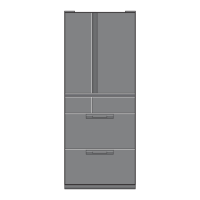
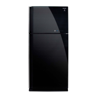
Identifies and names all major external and internal parts of the appliance.

2. Internal Structure

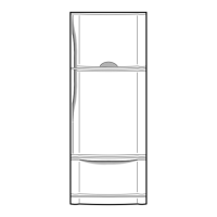
Explains the internal layout and components of the refrigerator.

3. Flow of Cool Air

Illustrates the path of cool air circulation within the appliance.

4. Temperature Distribution

Shows the temperature zones and expected values in different compartments.

Dimensions

1. Outer Dimensions and Clearance

Provides external measurements and required clearance for installation.

2. Inner Dimensions

Details the internal space measurements of the refrigerator compartments.

Electrical Circuit Diagrams

1. Wiring Diagram

Schematic showing electrical connections and wiring paths.

2. Electric Accessories Layout

Visual representation of the placement of electrical components.

3. Precautions for Using Lead-Free Solder

Guidelines for safely and effectively using lead-free solder for repairs.

Electrical System Specifications

1. Functional Part Specifications

Lists specifications for individual electrical components and their functions.

2. Mode for Display

Instructions on how to set, cancel, and operate the display mode.

Refrigeration Cycle System Specifications

1. R600a Precautions

Safety precautions and handling guidelines for R600a refrigerant.

2. Table of R600a Characteristics

Data table showing saturated vapor pressure characteristics for R600a.

3. Refrigeration Cycle Diagram

Visual representation of the refrigerant flow and system components.

3-1. Piping Diagram

Illustrates the detailed piping layout of the refrigeration system.

3-2. Schematic Diagram

A simplified schematic of the refrigeration circuit for clarity.

3-4. Specifications of Refrigerant Valve Operation

Details modes and fault conditions of the refrigerant valve.

Troubleshooting

1. Self-Diagnosis Mode

Explains how to enter, operate, and interpret the self-diagnosis system.

2. Forced Stopping of Door Alarm Buzzer

Procedure to temporarily disable the door open alarm buzzer.

3. Thermistor Circuit Check Method

Guide for checking thermistor resistance and voltage for diagnostics.

4. Inspection Flowchart and Repair Items

Step-by-step troubleshooting guide for common problems and error codes.

5. Plasmacluster OK/NG Judgment

Procedure to test and verify the functionality of the Plasmacluster unit.

Disassembly/Assembly

1. General Disassembly Sequence

Provides an overview of the order for disassembling major components.

2. Refrigerator Compartment Disassembly

Detailed steps for taking apart the refrigerator compartment.

3. Freezer Compartment / Ice Compartment Disassembly

Step-by-step guide for disassembling the freezer and ice compartments.

4. How to Remove Op. PWB Ass'y

Instructions for removing the operation printed wiring board assembly.

5. How to Remove Terminal Box

Procedure for safely removing the terminal box.

6. How to Install R-Sub Packing

Guide for correctly installing the R-sub packing on the door.

7. How to Install Duct RT Ass'y Cover

Instructions for fitting the Duct RT ass'y cover.

8. Adjustment of R-Door (Double Door)

Steps for adjusting the refrigerator doors for proper alignment and function.

9. Main Parts Assembly - EV Cover Ass'y

Assembly steps for the EV cover unit.

9. Main Parts Assembly - R-shower Duct Ass'y

Assembly steps for the R-shower duct assembly.

9. Main Parts Assembly - RC Box Ass'y

Assembly steps for the RC box assembly.

9. Main Parts Assembly - C-part. FI-FK

Assembly steps for the C-part. FI-FK component.

9. Main Parts Assembly - D-PCI Box Ass'y

Assembly steps for the D-PCI box assembly.

9. Main Parts Assembly - Ice Maker Ass'y T-SK

Assembly steps for the ice maker assembly.

9. Main Parts Assembly - Fruit Case Ass'y

Assembly steps for the fruit case.

9. Main Parts Assembly - Fan Motor G Ass'y

Assembly steps for the Fan motor G assembly.

Related product manuals