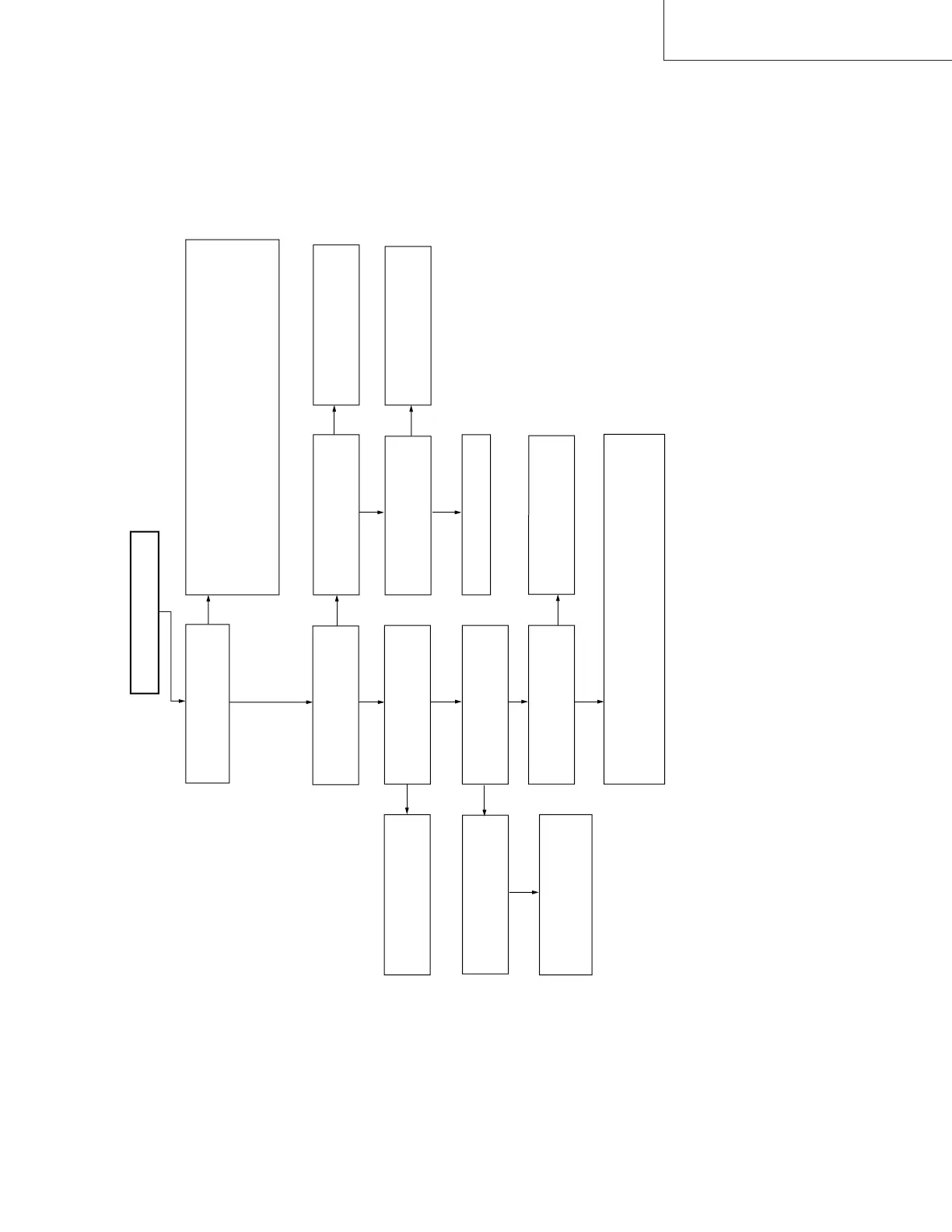
FLOW CHART NO.18 E-E MODE TROUBLESHOOTING
No picture E-E signal.
NO
NO
NO
NO
NO
YES
YES
YES
Is there picture signal inputt
to the pins(28), (30) and (31)
of IC201?
1For ext. input mode.
■Check line between rear video input terminal and pin(30) of IC201.
■Check line between front video input terminal and pin(28) of IC201.
2For U/V tuner mode.
■Check line between video output (pin 25) of TUNER and pin(31)
of IC201.
Is the supply voltage of 5V
(Y-Vcc) fed to pin(12) of
IC201?
Check Y/C 5V line.
Check line between pin(52) of
IC201, and pin(49) of IC701.
YES
YES
YES
YES
Is there a picture signal
outputted from the emitter of
Q251?
Check peripheral circuit of
Q251
NO
NO
Is there Y/C serial data and
Y/C clock signal applied to
pins(63) and (62) of IC201?
Check line between pins(63),
(62) of IC201 and pins(84),
(85) of IC701.
Is the supply voltage of 5V
(OSD-Vcc) fed to pin(51) of
IC701?
Replace IC201.
NO
Check MICON 5V line
(collector of Q704) and
Q704’s peripheral circuits.
1Line output : Check the line between Q251 peripheral and output
terminal periphery.
2RF output : Check the line between Q251 peripheral and RF
video input terminal of tuner periphery.
Is there a picture signal
output from the pin(52) of
IC201?
Is there a picture signal
inputted to the pin(49) of
IC701?
Is there a picture signal
outputted from the pin(47) of
IC701?