30
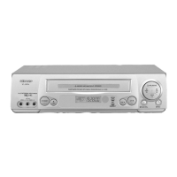
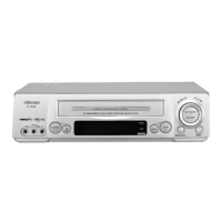
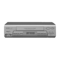
VC-MH75HM
Observe the video output using the osiloscope and con-
firm as the above diagram
* V:200mV/div
H:20µ sec/div
Measuring
instrument
Mode
Cassette
Spectrum
Analyzer
Record
Self-recorded tape
Test point YC CHIP Pin98
Specification 3.8MHz±50KHz
ADJUSTMENT OF FM Carrier Confirmation
VIDEO PAL Colour Bar(1Vp-p)
Measuring
instrument
Mode
Cassette
Osiloscope
Record
Self-recorded tape
(SP/EP mode)(See Note below)
Test point VIDEO OUT 21PIN or RCA Port
(75Ω Terminal)
Specification 1.0±0.2Vp-p
Y/C CIRCUIT ADJUSTMENT
ADJUSTMENT OF EE Level Confirmation
VIDEO PAL Colour Bar(1Vp-p)
Measuring
instrument
Mode
Cassette
Spectrum
Analyzer
Record
Self-recorded tape
Test point YC CHIP Pin98
Specification 4.8MHz±100KHz
ADJUSTMENT OF Deviation Confirmation
VIDEO Colour Bar(1Vp-p)
Measuring
instrument
Mode
Cassette
Osiloscope
Self-recorded/Playback tape
Test point YC CHIP Pin98
Specification about300mVp-p
ADJUSTMENT OF REC Current Confirma-
tion
VIDEO Colour Bar(1Vp-p)
1.0Vp-p
Record
<Diagram A>
Confirm the Sink chip is as the
left diagram <Diagram A>.
Sink Chip
3.80 4.80MHz
A
f
<Deviation>
Confirm the white peak frequency
follow the standard value.
(the deviation between shinkchip and
f white peak is 1MHz±100KHz)