VC;M H80
VC-M
H90
REMOVAL AND REASSEMBLY OF
CASSETTE HOUSING CONTROL ASSEMBLY
0
Removal
1. Set the cassette ejected condition in the cassette
eject mode.
2. Unplug-the recorder from the main source.
3. Follow the procedures below in the specified or-
der.
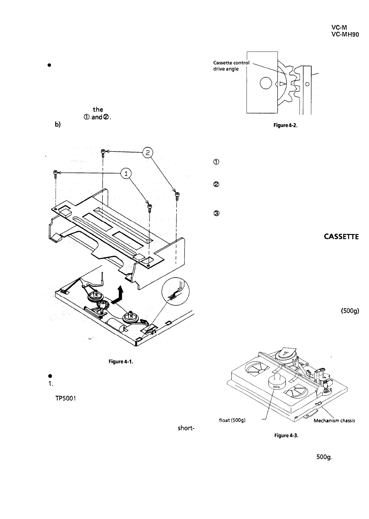
a) Remove ,the cassette housing installation
screws
@:and
@.
b)
Slide and pull out the cassette housing control
assembly upward.
0
1.
Figure
4-1.
Reassembly
Before installation of the cassette housing con-
trol assembly, make a short-circuit between
TP5001
and TP5002, both located on the timer
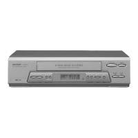
PWB. Plug in the power cord. The cassette con-
trol drive gear starts and stops just when a tally
mark appears in the mechanism chassis window.
Unplug the power cord, and remove the short-
circuit from between TP5001 and TP5002. Align
this tally mark with the cassette control drive an-
gle’s mark, as shown in Fig. 4-2, to position the
cassette control on the mechanism chassis.
Drive angle of
cassette
control
Figure
4-2.
2. Follow the procedures for removal in the reverse
order.
Notes:
0
In using a magnet screw driver, be sure to keep it
away from the A/C head, FE (Full Erase) head, or
the drum.
8
In removal and reassembly, take care not to hit
the cassette housing control assembly or tools
against the guide pin, drum, or the like there-
about.
@
Load the cassette once onto the cassette housing
control assembly after reassembly.
TO RUN A TAPE WITHOUT THE
CASSElTE
HOUSING CONTROL ASSEMBLY
1. Be sure to make a short-circuit between TP5001
and TP5002, both located on the timer PWB, be-
fore turning on the power.
2. Plug in the power cord.
3. Turn on the power switch.
4. Open the lid of a cassette tape by hand.
5. Hold the lid with two pieces of vinyl tape.
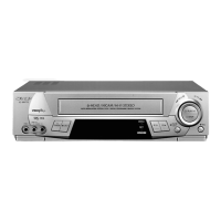
6. Set the cassette tape in the mechanism chassis.
7. Stabilize the cassette tape with a weight
(5009)
to prevent floating.
8. Perform running test.
Weight to prevent
Figure
4-3.
Note:
The weight should not be more than
5009.
13