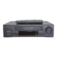
VC-MH80
VC-MH90
REPLACEMENT AND
HEIGHTCHECKING
AND ADJUSTMENT OF REEL DISKS
l
Removal (Supply and Take-up reel disks)
1. Remove the cassette housing control assembly.
2. Pull the tension band out of the tension arm. .
3.
Remove
the supply main
brake and the take-up
main
brake.
4. Open the hook at the top of the reel disk, and
remove the reel disk.
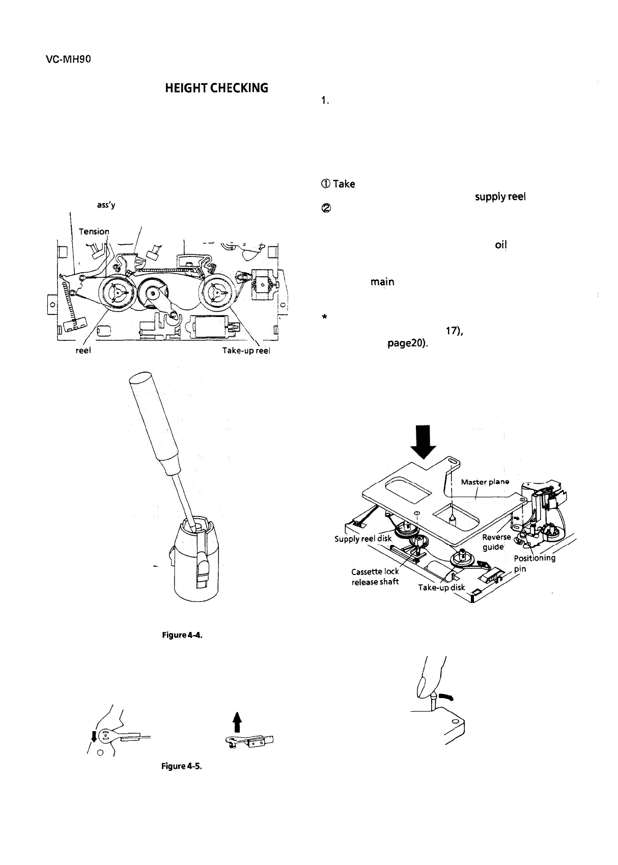
Tension arm
ass’y
I
Supply main brake
Take-up main brake
Tensio:
band
/
I
Supply
re’el
disk
Take-up:eel
disk
l
Reassembly (Supply reel disk)
1.
Clean the reel disk shaft and apply oil to it.
2. Install a new supply reel disk onto the shaft.
3. Replace the tension band around the supply reel
disk, and insert it to the hole of the tension arm.
4 Check the reel disk height and reassemble the
supply main brake.
Notes:
@Take enough care not to deform the tension
band during installation of the supply,reel disk.
@
Be
careful
not to damage the supply main brake.
l
Reassembly (Take-up reel disk)
1. Clean the reel disk shaft and apply
oi!
to it.
2. Install a new take-up reel disk onto the shaft.
3. Check the reel disk height and reassemble the
take-up main brake.
Note:
Take care not to damage the take-up main brake.
*
After reassembly, check the video search rewind
back tension (see page
17),
and check the brake
torque (see ‘page20).
l
Height checking and adjustment
Note:
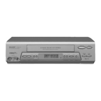
Place the master plane onto the mechanism unit,
taking care not to hit the drum (see Figure 4-6).
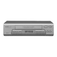
Figure
4-4.
Set the master plane releasing
the reverse guide by a finger.
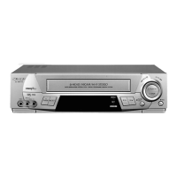
Note:
When the tension band is pressed in the direction
of the arrow for removal, the catch is hard to be de-
formed.
JYf3L
4
Reverse guide
Figure
4-5.
t
N
14
Master plane
Figure 4-6.