36
VT-G14
VT-G21
3. Align the left end of gear of A/C head plate with the
punched mark of chassis, tentatively tighten the
screws 1 and 2 so as to ensure smooth motion of
A/C head plate. Tentative tightening torque must be
0.15 to 0.20 N·m (1.5 to 2.0kgf·cm).
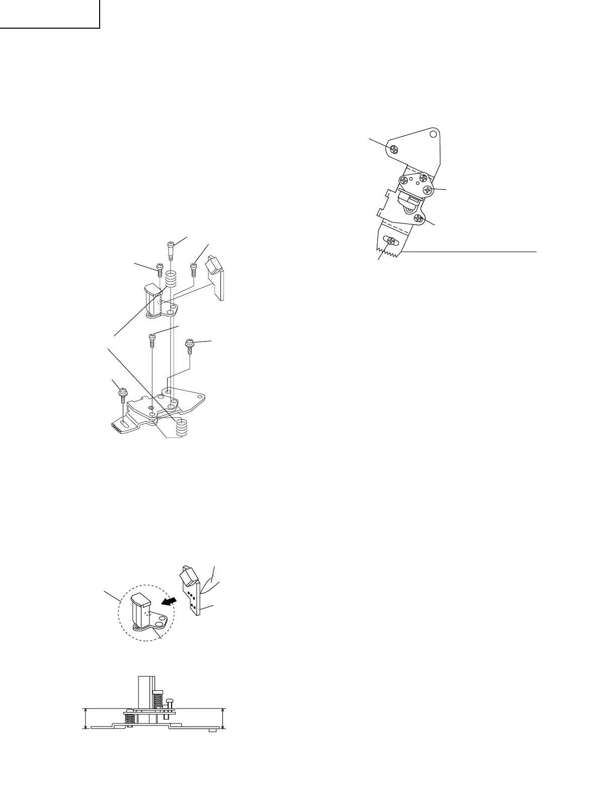
Height screw
Figure 1-23.
Figure 1-24.
Figure 1-25.
3
Azimuth screw
1
2
Spring
Tilt screw
New A/C head ass'y
∗
Never touch the head
A/C head base
A/C head PWB
Solder
10.8mm
10.8mm
Left end of A/C head plate gear
Punched line mark on chassis
Height screw
1
3
2
Notes:
1. If the screws 1 and 2 are tighten tentatively too
loose, the azimuth and height of A/C head may
change when they are finally tightened. Therefore
care must be taken.
2. After completion of A/C head be sure to adjust tape
running. (Execute the running adjustment by the
method described in Pages 38 and 39.)
• Replacement
1. Solder the removed PWB to the new head assembly.
2. Adjust the height from the A/C head plate (lower
surface) to the A/C head base to 10.8mm with slide
calipers. (3 places of azimuth screw section, tilt screw
section and height screw section)(See the figure
below.)
REPLACEMENT OF A/C (Audio/Control)
HEAD
1. Remove the cassette housing control assembly.
2. In unloading state unplug the power cord.
• Removal
1. Remove the screws 123, Azimuth screw and
Tilt screw.
2. Unsolder the PWB fitted to the A/C head
Notes:
1. When replacing, never touch the head. If you touched,
clean with the cleaning liquid.
2. When removing the screw 3, take care so that the
spring may spring out.