7
VT-G14
VT-G21
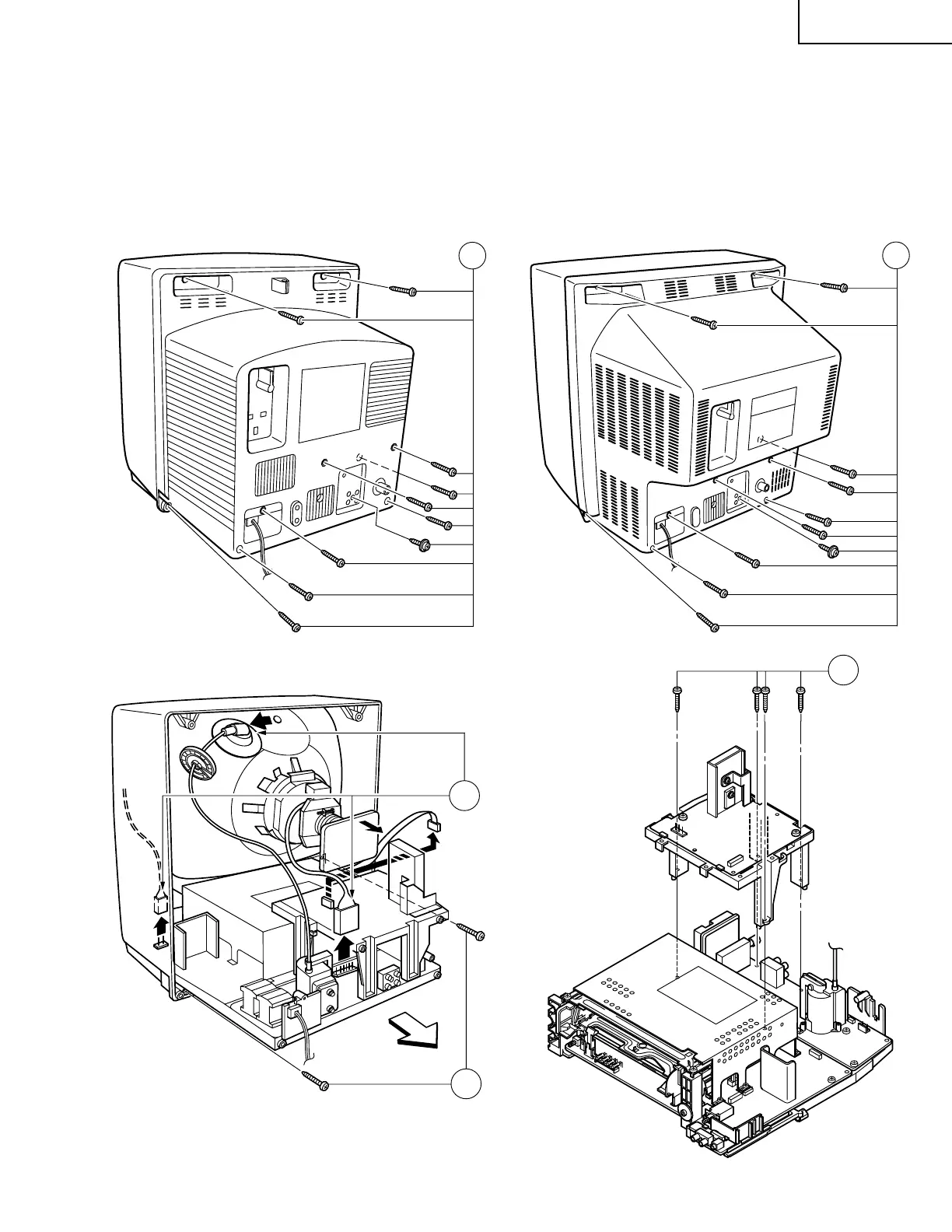
DISASSEMBLY AND REASSEMBLY
1. Remove the 10 rear cover fixing screws and detach the rear cover.
2. Take out the anode cap, CRT PWB, connectors F, G and AO, coating ground, SP chip, fixing screws and others.
3. Remove the 2(VT-G14)/1(VT-G21) Main PWB fixing screws and take out the Main PWB unit and the Power PWB.
4. Remove the 4 Power PWB fixing screws, and take out the Power PWB unit.
G
3
F
AO
2
(VT-G14 only)
1
1
VT-G21
VT-G14