8
VT-G14
VT-G21
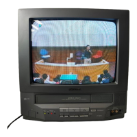
DISASSEMBLY AND REASSEMBLY (Continued)
5. Remove the 7 VCR fixing screws, and detach the shielding case.
6. Remove the 4 cassette housing control fixing screws, and detach the cassette housing control.
7. Remove the 4 mechanism chassis fixing screws, and detach the mechanism chassis from the Main PWB.
8. Remove the 3 Main PWB fixing screws, and detach the Main PWB.
9. Remove the 4 Tuner/Def and IF PWB fixing screws, and detach the Tuner/Def and IF PWB.
5
6
7
7
7
8
9