41
VT-G14
VT-G21
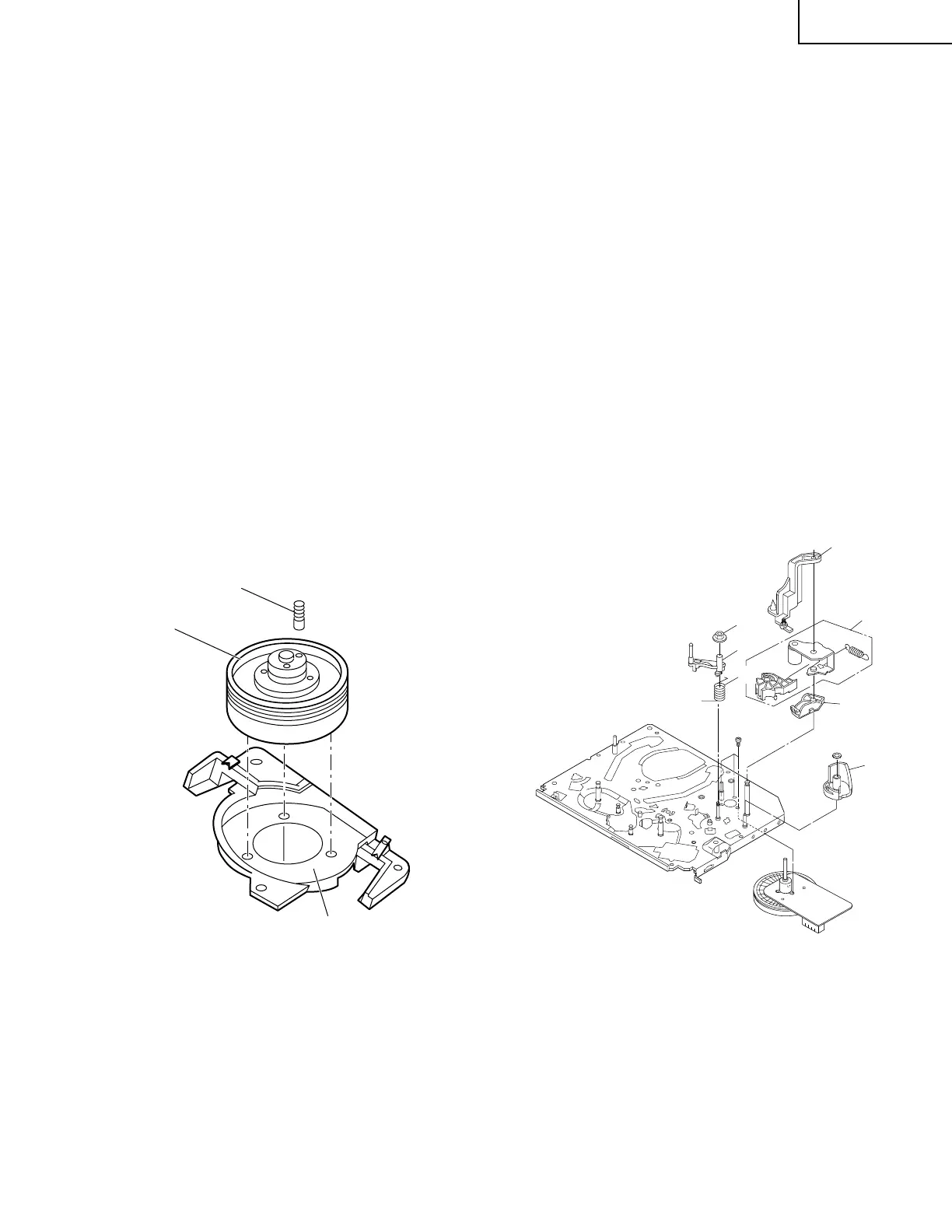
REPLACING THE UPPER AND LOWER
DRUM ASSEMBLY
• Replacement (Perform in the numerical order)
1 Remove the motor as stated in Page 40 D.D. motor
replacement.
2 Remove the drum earth brush 2.
3 Remove the drum base 3 from the upper and lower
drum assembly 1.
[Cares when replacing the drum]
1. Be careful so that the drum earth brush is not lost.
2. Do not touch directly the drum surface.
3. Fit gently the screwdriver to the screws.
4. Since the drum assembly is an extremely precise
assembly, it must be handled with utmost care.
5. Make sure that the drum surface is free from dust, dirt
and foreign substances.
6. After replacing the drum be sure to perform the tape
running adjustment.
After that, perform also the electrical adjustment.
• Playback switching point adjustment
• X-position adjustment and check
7. After replacing the drum clean the drum.
Figure 1-39. Figure 1-40.
ASSEMBLING OF PHASE MATCHING
MECHANISM COMPONENTS
• Assemble the phase matching mechanism com-
ponents in the following order.
1. Assemble the pinch roller assembly and pinch drive
cam.
2. Mounting the shifter (on the back of the mechanism
chassis).
3. Mounting the master cam (on the back of the mecha-
nism chassis).
4. Assemble the connection gear, slow brake and load-
ing motor parts.
• Pinch drive cam and pinch roller assembling
method.
(Place the following parts in position in numeri-
cal order.)
(1)Reverse drive lever 1
(2)Reverse guide spring 2
(3)Reverse guide lever ass’y 3
(4)Reverse guide height adjusting nut 4
(5)Pinch drive cam 5
(6)Pinch roller ass’y 6
(7)Open lever 7
2
1
3
7
6
4
3
2
1
5