– 7 –
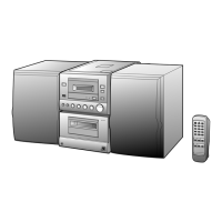
XL-520W/CP-520
1 Top Cabinet 1. Screw .................. (A1) x4 7-1
2. Socket ................. (A2) x3
3. Screw .................. (A3) x1
2 Side Panel 1. Screw .................. (B1) x7 7-1
(Left/Right)
3 Back Board 1. Screw .................. (C1) x4 7-1
(With Power 2. Socket ................. (C2) x2
Amp. PWB) 3. Flat Wire .............. (C3) x1
4 Main PWB 1. Screw .................. (D1) x3 7-2
2. Socket ................. (D2) x2
5 Front Panel 1. Screw .................. (E1) x2 7-2
6 Display PWB/ 1. Screw .................. (F1) x6 7-2
CD Servo PWB 2. Socket ................. (F2) x2
7 Power Supply PWB 1. Screw .................. (G1) x5 7-2
8 Jack PWB 1. Screw .................. (H1) x1 7-3
9 Tape Mechanism 1. Screw .................. (J1) x4 7-3
10 CD Mechanism 1. Screw .................. (K1) x3 7-4
DISASSEMBLY
Caution on Disassembly
Follow the below-mentioned notes when disassembling
the unit and reassembling it, to keep it safe and ensure
excellent performance:
1. Take cassette tape and compact disc out of the unit.
2. Be sure to remove the power supply plug from the wall
outlet before starting to disassemble the unit.
3. Take off nylon bands or wire holders where they need be
removed when disassembling the unit. After servicing
the unit, be sure to rearrange the leads where they were
before disassembling.
4. Take suffcient care on static electricity of integrated
circuits and other circuits when servicing.
Figure 7-2
Figure 7-3
STEP REMOVAL
PROCEDURE
FIGURE
Figure 7-1
XL-520W
STEP
REMOVAL PROCEDURE FIGURE
1 Woofer 1. Net........................... (A1) x1 7-5
3. Screw ...................... (A2) x4
CP-520