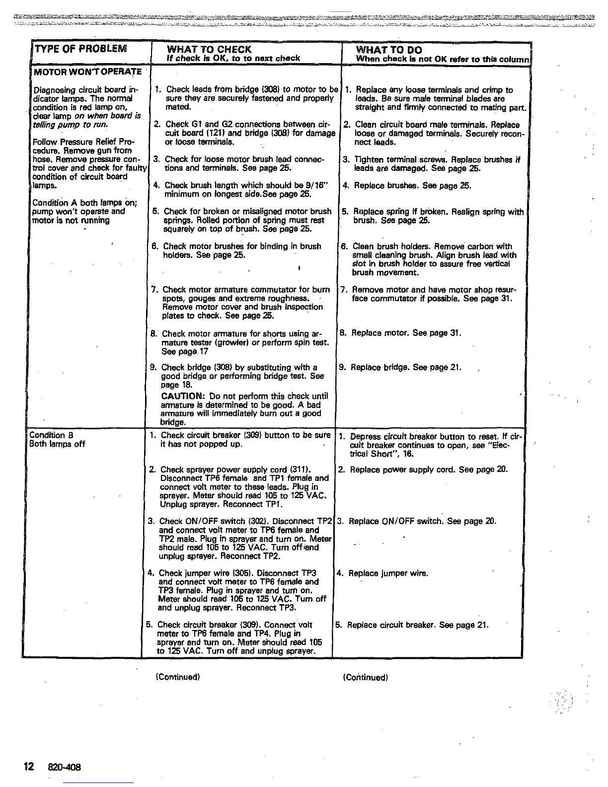
HOTOR
WONTOPERATE
Iiagnosing circuit board
in-
Iicator lamps. The normal
andition is red lamp on,
$ear lamp
on
when
board
I
elling
pump
to
run.
:allow
Pressure Relief
Pro-
ndure. Remove gun from
lose. Remove pressure cor
rol
cover and check for fat
ondition
of
circuit board
mps.
:ondtion
A both lamps
On;
lump won't operate and
mor
is
not
running
Dndition
8
fh lamps
off
refer
to
*is colu~
sure they are securelyjastened and properl)
mated.
1.
Check leads from bridae
13081
to motor
to
be
1.
Replace any
loose
terminals and crimp to
I
leads. Be sure male terminal blades are
straight and firmly connected to mating pa
2.
Check
G1
and
62
connections between cir-
or
loose
terminals.
cuit board
1121)
and bridge
1308)
for damagl
3. Check for loose motor brush lead wnnec-
tions
and terminals. See page
25.
4.
Check brush length which should
be
9/16"
minimum on longest side.Sea page
25.
5.
Check for broken or misaligned motor brush
squarely on top of brush. See page
25.
springs.
Rolled
portion
of
spring must
rest
6.
Check motor brush& for binding in brush
holders. See page
25.
I
7.
Check moior armature commutator for burn
spots, gouges and extreme roughness.
plates to check. See page
25.
Remove motor cover and brush inspenion
3.
Check motor armature for shorts using ar-
mature tester (growler) or perform spin test.
See page
17
good bridge or performing bridge
test.
See
page
18.
CAUTION:
Do
not
perform this check until
armature
is
determined to be good. A bad
armature will immediately bum out
a
good
bridge.
I.
Check circuit breaker
(309)
button to be sure
it
has not popped up.
3.
Check bridge
(308)
by substituting with
a
!.
ChecA sprayer power supply cord (31
1).
Disconnect TP6 female and TP1 female and
sprayer. Meter should read
105
to
125
VAC.
connect volt meter to these leads. Plug in
Unplug sprayer. Reconnect
TPl.
.
Check
ON/OFF
switch
13MI.
Disconnect TP2
~ ~~ ~
and connect volt meter to TP6 female and
should read
105
to
125
VAC. Turin offand
TP2
male. Plug in sprayer and turn on. Meter
,
~~~.
unplug sprayer. Reconnect TPZ.
.
Check jumper wire
1305).
Disconnect TP3
and connect volt meter to TP6 female and
TP3 female. Plug
In
sprayer and turn on.
and unplug sprayer. Reconnect TP3.
Meter should read
106
to
125
VAC. Turn
off
meter to TP6 female and TP4. Plug
in
Check circuit breaker
(309).
Connect volt
sprayer and turn on. Meter should read
105
to
125
VAC. Turn
off
and unoiuo soraver.
1
i
2.
Clean circuit board male terminals. Replacl
loose or damaged terminals. Securely reco
nect leads.
3. Tighten terminal
screws.
Replace brushes
i
leads are damaged.
Sea
page
25.
4.
Replace brushes.
Sea
page
25.
5.
Replace spring
if
broken. Realign spring
wi
brush. See page
25.
6.
Clean brush hoiders. Remove carbon
with
slot in brush holder to assure free vertical
SWall
cleaning brush..Align brush lead with
brush movement.
7.
Remove motor and have motor shop resur-
face commutator
if
possible. See page 31.
8.
Replace motor. See page 31.
3.
Replace bridge. See page
21.
I.
Depress circuit breaker bunon to reset.
If
cil
cuit breaker continues to
open,
see
"Elec-
trical Short",
16.
?.
Replace power supply cord.
See
page
20.
I.
Replace
ON/OFF
switch.
See
page
20.
..
..
Replace jumper wire.
.
Replace circuit breaker.
See
page
21.
Continued)
(Continued)
.::
!
..
.. .
.,
..
 Loading...